


Chapter 4 Theory of Operation
BNC-2140 User Manual 4-2
©
National Instruments Corporation
Functional Overview
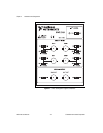
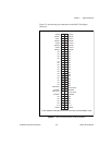
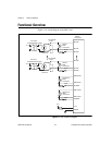
Figure 4-1 is a block diagram of the BNC-2140.
Figure 4-1.
BNC-2140 Block Diagram
0
+5 V +30 V
ICP CH0
Isolated Power Supply
ICP Current
Source 0
ICP Enable
on/off
AICH0
BNC
Connector
DIFF/SE
50 Ω
AICH0+
AICH0–
AIGND
3
+5 V +30 V
ICP CH3
Isolated Power Supply
ICP Current
Source 3
ICP Enable
on/off
AICH3
BNC
Connector
DIFF/SE
50 Ω
AICH3+
AICH3–
AIGND
DAC0OUT
BNC
Connector
DIFF/SE
50 Ω
DAC0OUT+
DAC0OUT–
AOGND
DAC1OUT
BNC
Connector
DIFF/SE
50 Ω
DAC1OUT+
DAC1OUT–
AOGND
68-Pin
Connector
+5 V
DGND
+5 V
ICP Power
on/off