


© National Instruments Corporation I-1 FieldPoint FP-1000/FP-1001 User Manual
Index
A
ACCESS LED, 3-7
addresses, setting
address and baud rate, 2-9 to 2-10
network address, 2-10 to 2-11
unique address for each module (note), 2-10
B
banks. See FieldPoint banks.
baud rate
address and baud rate switch settings
(figure), 2-9
baud rate switch settings (figure), 2-12
setting for network module, 2-9 to 2-10
biasing resistors for RS-485 port, 2-8
BridgeVIEW software, using with FieldPoint
Server, 4-2
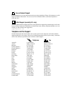
bulletin board support, B-1
bus, high-speed local, 3-1
C
configuration of network module, 2-9 to 2-12.
See also installation.
address and baud rate selection, 2-9 to 2-10
baud rate settings, 2-12
network address settings, 2-10 to 2-11
connections
network connections
FP-1000, 2-3 to 2-4
FP-1001, 2-4 to 2-5
serial port connections, 2-5 to 2-9
isolation of RS-485 interface (note),
2-5 to 2-6
RS-232 interface specifications,
2-6 to 2-7
RS-485 interface specifications,
2-7 to 2-9
terminal base connection, 2-2 to 2-3
connector pinouts
power connector (figure), 2-13
RS-232 ports (figure), 2-6
RS-485 ports (figure), 2-7
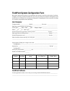
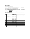
customer communication, B-1 to B-2, xi
D
DIN rail clip
installing network module (figure), 2-1
locking FieldPoint network module
(figure), 2-2
unlocked position (figure), 2-1
documentation
conventions used in manual, x-xi
how to use manual set, ix
organization of manual, x
related documentation, xi
E
electronic support services, B-1 to B-2
e-mail support, B-2
environment specifications, A-2
error conditions indicated by STATUS LED
(table), 3-8