


© National Instruments Corp. 5 FP-QUAD-510
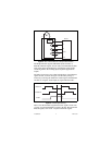
Terminal assignments and wiring diagrams are also listed under the
slide-in card on the front of the FP-QUAD-510 module.
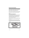
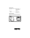
Status Indicators
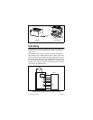
Figure 5 shows the module label and status indicators. Remove the
slide-in card to see wiring diagrams for the input signals.
Figure 5.
Status Indicators
After you insert the module into a terminal base (and apply power),
the green POWER indicator lights and the FP-QUAD-510 informs
the network module of its presence. When the network module
recognizes the FP-QUAD-510, it sends initial configuration
information to the FP-QUAD-510. After receiving this initial
information, the green READY indicator lights and the
FP-QUAD-510 is in its normal operating mode.
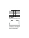
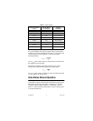
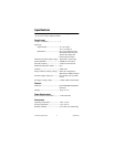
Table 1.
Terminal Assignments
Signal
Terminal Numbers
Axis 0 Axis 1 Axis 2 Axis 3
+A 1 5 9 13
–A 17 21 25 29
+B 2 6 10 14
–B 18 22 26 30
+I 3 7 11 15
–I 19 23 27 31
Vsup 4 8 12 16
COM 20 24 28 32