


FP-RLY-420 10 www.natinst.com
•Do not share the external supply voltages (V and C on the
terminal base) with other devices (including other FieldPoint
devices) unless those devices are also isolated from human
contact.
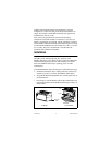
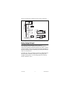
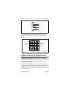
• As with any hazardous voltage wiring, ensure that all wiring
and connections meet with applicable electrical codes or
common sense practices. Mount terminal bases in an area,
position, or cabinet that prevents accidental or unauthorized
access to wiring with hazardous voltages.
• The isolation of the FP-RLY-420 is certified as double
insulated for normal operating voltages of 250 Vrms. Do not
use the FP-RLY-420 as the sole isolating barrier between
human contact and working voltages of more than 250 Vrms.
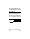
Specifications
The following specifications are typical for the range
–40 to +70 °C, unless otherwise noted.
Input Characteristics
Number of channels..........................8
Relay type.........................................1 Form A (SPST)
Nonlatching
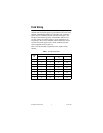
Maximum Switching Capacity (Resistive Load)
AC ..............................................3 A at 250 VAC
DC ..............................................3 A at 35 VDC
2 A at 40 VDC
1 A at 55 VDC
0.4 A at 120 VDC
Note
Above 55 °C ambient, max. 1.5 A per channel.
Minimum switching voltage.............10 mA at 5 VDC
On resistance.....................................100 mΩ
Off state leakage ...............................0.3 µA at 250 VAC
Expected Life
Mechanical .................................20
×
10
6
operations min.
Electrical (at 30 cpm).................300,000 operations at 3 A,
35 VDC
100,000 operations at 3 A,
250 VAC