


© National Instruments Corp. 5 FP-RTD-124 and cFP-RTD-124
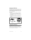
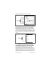
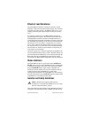
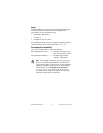
Figure 3 shows the input circuitry on one channel.
Figure 3. FP-RTD-124 Input Circuit
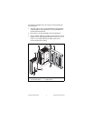
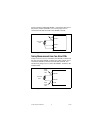
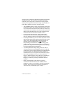
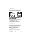
Taking Measurements from Four-Wire RTDs
Four-wire RTDs generally have two wires of one color and two of
another color (usually red and white). Connect the wires of one
color to the positive terminals (EXCITE+ and SENSE+). Connect
the wires of the other color to the negative terminals (COM and
SENSE–).
Figure 4. Four-Wire RTD Connections on One Channel
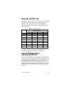
Taking Measurements from Three-Wire RTDs
NI recommends the [c]FP-RTD-122 for three-wire RTD
measurements because it includes special sensing circuitry to
compensate for up to 95% of the lead resistance of the third wire.
Most three-wire RTDs have two wires of one color (usually red,
sometimes black) and one wire of another color (usually white,
sometimes red). Connect the two wires of the same color to the
SENSE+
[c]FP-RTD-124
SENSE–
COM
EXCITE+
Amplifier
Pulsed 2 mA
Four-Wire
RTD
16-bit
ADC
SENSE+
[c]FP-RTD-124
SENSE–
COM
EXCITE+
Four-Wire
RTD