Chapter 1 Introduction
© National Instruments Corporation 1-3 VXI-1394 User Manual for Windows
Caution An improper Slot 0 setting may damage the VXI-1394 module and/or the VXI
chassis.
The VXI-1394 links the computer to the VXIbus and converts 1394 data
transfers into VXIbus data transfers and vice versa. The VXI-1394 includes
additional 1394 ports you can use to connect other 1394 devices.
The PCI-1394 is an industry-standard 1394 host adapter on a PCI board,
which gives your computer the capability to control 1394 devices. The
PCI-1394 also supplies power to the IEEE 1394 bus, which is required by
some devices.
VXI-1394 Front Panel Features
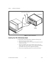
The VXI-1394 has the following front panel features.
• Three front panel LEDs
– SYSFAIL LED indicates that the VMEbus SYSFAIL line is
asserted.
– 1394 LED indicates when the VXI-1394 is accessed from the
IEEE 1394 bus.
– VXI LED indicates when the VXI-1394 is accessed from the
VXIbus.
• Three 1394 6-pin connectors
• Three SMB connectors
– External clock
– Trigger output
– Trigger input
• System reset push-button
Advanced Configuration Options
The default hardware configuration of the VXI-1394 should be
acceptable for most systems. Refer to Appendix C, Advanced Hardware
Configuration Settings, only if your system will make use of the front-panel
CLK10 and trigger SMB connectors.


