


Chapter 8 PFI
NI 6232/6233 User Manual 8-2 ni.com
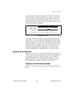
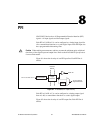
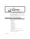
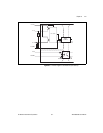
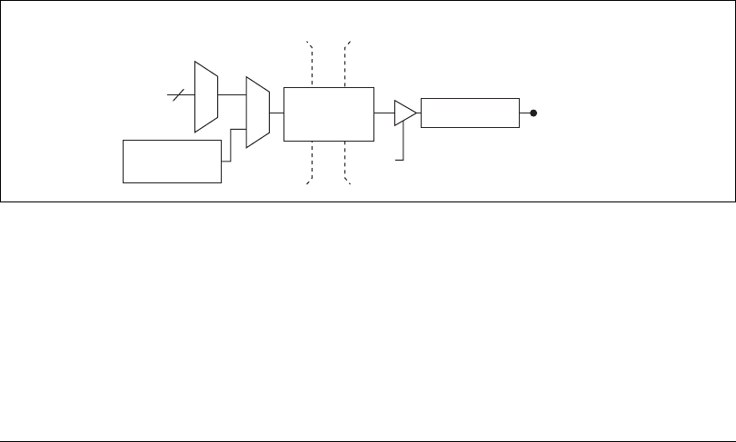
Figure 8-2. NI 6232/6233 PFI Output Circuitry
When a terminal is used as a timing input or output signal, it is called PFI x
(where x is an integer from 0 to 9). When a terminal is used as a static digital
input or output, it is called P0.x or P1.x.
The voltage input and output levels and the current drive levels of the PFI
signals are listed in the NI 6232/6233 Specifications.
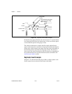
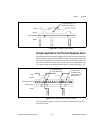
Using PFI Terminals as Timing Input Signals
Use PFI <0..5> terminals to route external timing signals to many different
M Series functions. Each input PFI terminal can be routed to any of the
following signals.
• AI Convert Clock
• AI Sample Clock
• AI Start Trigger
• AI Reference Trigger
• AI Pause Trigger
• AI Sample Clock Timebase
•AO Start Trigger
• AO Sample Clock
• AO Sample Clock Timebase
• AO Pause Trigger
• Counter input signals for either counter—Source, Gate, Aux,
HW_Arm, A, B, Z
Most functions allow you to configure the polarity of PFI inputs and
whether the input is edge or level sensitive.
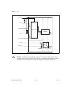
Timing Signals
I/O Protection
PFI <6..9>/P1.<0..3>
Output
Enable
Static DO
Buffer
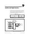
Isolation
Barrier
Digital
Isolators
Note: One output enable is shared
by all digital output signals.