


Chapter 3 Hardware Overview
© National Instruments Corporation 3-3 MXI-Express Series User Manual
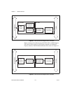
Functional Unit Descriptions
PCI Express x1 Card Edge Connector
The card edge connector allows you to use the NI PCIe-836x in a x1 or
wider PCI Express slot in a PC. The PCI Express Card Electromechanical
Specification defines this connector.
PCI Express x1 Switch
The PCI Express Base Specification defines a PCI Express switch as a
logical collection of PCI Express-to-PCI Express bridge devices. On the
NI PCIe-8362, the upstream port of the switch is connected to the
PCI Express x1 card edge connector, and the two downstream ports are
connected to the two cabled PCI Express connectors.
Cabled PCI Express Connector
The cabled PCI Express connector provides all necessary signals to connect
an NI PCIe-836x and an NI PXI-8360. These signals include the
PCI Express transmit and receive pair, the system clock, and a presence
detect signal.
PCI Express-to-PCI Bridge
The PCI Express Base Specification defines a PCI Express-to-PCI bridge
as a device that connects a PCI Express fabric and a PCI hierarchy. On the
NI PXI-8360, the PCI Express-to-PCI bridge connects the x1 PCI Express
link and the PCI bus in a PXI or CompactPCI chassis.
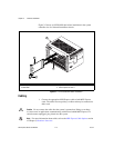
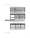
LED Indicators
The LEDs on MXI-Express give status information about power supplies
and link state. The NI PCIe-8362 has two tri-color LEDs, one for each port
on the panel. The NI PXI-8360 has two LEDs, one for power supply status
and one for link state.