


© National Instruments Corporation 9 NI USB-6221/6229/6251/6259 OEM User Guide
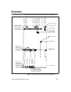
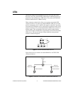
LEDs
USB-6221/6229/6251/6259 OEM devices have two LEDs that reflect
the device state. The green READY LED indicates whether the device is
powered on and configured as a USB device. The yellow ACTIVE LED
indicates whether there is USB bus activity.
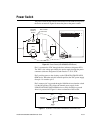
Three connectors on the device allow you to connect an external LED
circuit to the device. To connect an external READY LED, use E1 as the
positive connection (+3.3 V) and E2 as the negative connection. To connect
an external ACTIVE LED, use E1 as the positive connection and E3 as the
negative connection. E1 is current limited with a 100 Ω resistor to the 3.3 V
internal supply. This configuration limits the current to approximately
16 mA into a single external LED or approximately 8 mA each when both
LEDs are on. You also can limit this current further by using external
resistors as shown in Figure 8.
Figure 8. USB-6221/6229/6251/6259 OEM LEDs
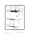
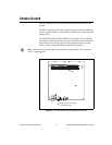
Figure 9 shows how to connect an external READY or ACTIVE LED
circuit to the device.
Figure 9. Schematics of the USB-6221/6229/6251/6259 OEM LEDs
DS1
E3
E2 E1
E1
100 Ω
Internal
3.3 V
External
READY LED
External
ACTIVE LED
E2
External Resistor
E3
External Resistor