© National Instruments Corporation 17 NI USB-6008/6009 User Guide and Specifications
Analog Input
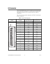
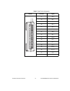
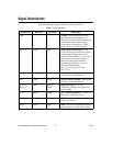
You can connect analog input signals to the NI USB-6008/6009 through
the I/O connector. Refer to Table 6 for more information about connecting
analog input signals.
Analog Input Circuitry
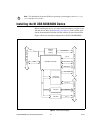
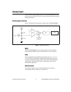
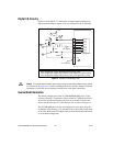
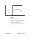
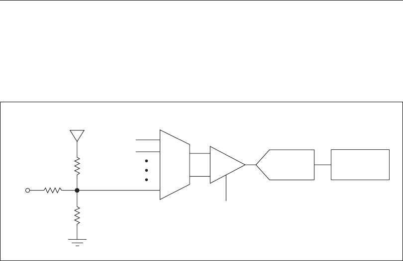
Figure 7 illustrates the analog input circuitry of the NI USB-6008/6009.
Figure 7. Analog Input Circuitry
MUX
The NI USB-6008/6009 has one analog-to-digital converter (ADC).
The multiplexer (MUX) routes one AI channel at a time to the PGA.
PGA
The progammable-gain amplifier provides input gains of 1, 2, 4, 5, 8,
10, 16, or 20 when configured for differential measurements and gain
of 1 when configured for single-ended measurements. The PGA gain is
automatically calculated based on the voltage range selected in the
measurement application.
A/D Converter
The analog-to-digital converter (ADC) digitizes the AI signal by
converting the analog voltage into a digital code.
AI
+2.5 V
REF
39.2 kΩ
127 kΩ
30.9 kΩ
PGA
Input Range
Selection
AI FIFO
ADC
MUX


