


© National Instruments Corporation 1-1 NI-VXI User Manual
Overview of NI-VXI
Chapter
1
This chapter introduces you to the concepts of VXI (VME eXtensions
for Instrumentation), VME, MXI (Multisystem eXtension Interface),
and their relationship to the NI-VXI application programmer’s
interface (API).
Comprehensive functions for programming the VXIbus/VMEbus are
included with the NI-VXI software. They are available for a variety of
controller platforms and operating systems. Among the compatible
platforms are the National Instruments line of embedded controllers
and external computers that have a MXIbus interface.
Note:
The following chapter discusses features unique to VXI as well as
common VXI/VME features. VME users can skip to the section entitled
Interrupts and Asynchronous Events.
VXIbus Overview
Concepts of the VXIbus specification include the VXI device,
message-based devices, the World Serial Protocol, the
Commander/Servant hierarchy, and hardware interrupts and
asynchronous events.
VXI Devices
A VXI device has a unique logical address, which serves as a means of
referencing the device in the VXI system. This logical address is
analogous to a GPIB device address. VXI uses an 8-bit logical address,
allowing for up to 256 VXI devices in a VXI system.
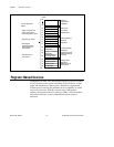
Each VXI device must have a specific set of registers, called
configuration registers (Figure 1-1) .These registers are located in the
upper 16 KB of the 64 KB A16 VME address space. The logical
address of a VXI device determines the location of the device’s
configuration registers in the 16 KB area reserved by VXI.