


Chapter 3 I/O Information
© National Instruments Corporation 3-3 NI PXI-8105 User Manual
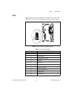
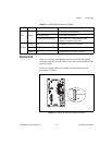
DVI-I
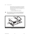
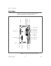
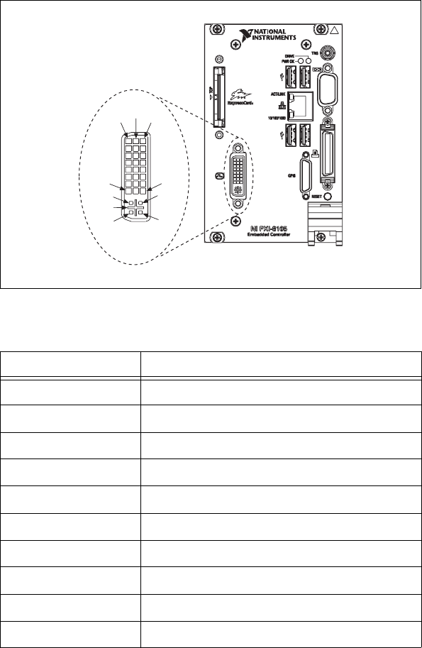
Figure 3-2 shows the location and pinouts for the DVI-I connector on the
NI PXI-8105. Table 3-2 lists and describes the DVI-I connector signals.
Figure 3-2. DVI-I Connector Location and Pinout
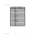
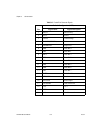
Table 3-2. DVI-I Connector Signals
Pin Signal Name
1 TMDS Data2–
2 TMDS Data2+
3 TMDS Data2/4 Shield
4 Reserved
5 Reserved
6 DDC Clock [SCL]
7 DDC Data [SDA]
8 Analog vertical sync
9 TMDS Data1–
10 TMDS Data1+
1
9
17
C4
8
24
C3
C2
C1
C5