


SCC-CO20 Isolated Current Output Module User Guide 14 ni.com
SCC-CO20 Module Pin Assignments
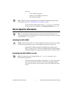
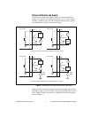
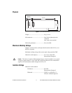
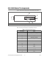
Figure 7 shows the I/O connector pins on the bottom of the module.
Figure 7. SCC-CO20 Bottom View
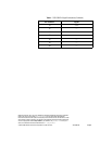
Table 1 lists the signal connection corresponding to each pin.
1Pin 1 2Pin 2 3 PWB Key 4 Pin 19 5Pin 20
Table 1. SCC-CO20 Pin Signal Connections
Pin Number Signal
1 E/M Series AO (X)
2 E/M Series AO GND
3 —
4 E/M Series AO GND
5 —
6 —
7 —
8 —
9 +5 V
10 GND
11 —
12 +5 V REF
13 +15 V
5
4
2
1
3