


© National Instruments Corporation 3 SCC-RLY01 Relay Module User Guide
– Documentation for your hardware
– Documentation for your software
❑ Tools
– 1/8 in. flathead screwdriver
– Numbers 1 and 2 Phillips screwdrivers
– Wire insulation stripper
You can download NI documents from
ni.com/manuals. To download
the latest version of NI-DAQ, click Download Software at
ni.com.
Note Configuring the SCC system using Measurement & Automation Explorer (MAX) is
not supported on the Macintosh operating system.
Device Specific Information
Note For general SCC module installation and signal connection information, and
information about the SCC-68 or SC-2345 carrier, refer to the SCC Quick Start Guide,
available for download at
ni.com/manuals.
Installing the Module
Caution Refer to the Read Me First: Safety and Radio-Frequency Interference document
before removing equipment covers or connecting/disconnecting any signal wires.
Plug the SCC-RLY01 into any DIO socket J(X+9), where X is 0 to 7, on the
SC-2345, or into any of the four slots that correspond to P0.0 to P0.3 on the
SCC-68.
Connecting the Input Signals
Note The signal names have changed. Refer to ni.com/info and enter rdtntg
to confirm the signal names.
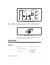
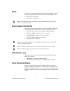
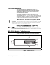
Each screw terminal is labeled by pin number <1..3>. Pin 1 is the
NC terminal, pin 2 is the COM terminal, and pin 3 is the NO terminal.
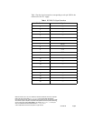
The SCC-RLY01 contains one SPDT relay controlled by the digital line of
an E/M Series DAQ device P0. line X. The value of X is determined by the
number of the DIO socket, J(X+9) on the SC-2345 or SCC Mod (X + 1) on
the SCC-68, where you plug in the SCC-RLY01. Figure 1 shows a circuit
diagram of the SCC-RLY01.