


NEC Display Solutions of America, Inc.
NP40/50/60 Installation Guide
Ceiling Mounted and Desktop Rev 1.2
______________________________________________________________________________________________________________________
www.necdisplay.com NP40/50/60 Page 2 of 6
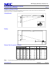
Diagrams and Distance Charts
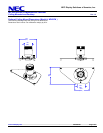
The following diagrams show the relationship between projector position and the screen. Refer to the chart below for data.
Distances are in inches. For millimeters multiply by 25.4.
Ceiling Mounted
Desktop
B
C
Lens Ctr
Screen Ctr
Throw Distance
Screen Top
4.75"
5.71"
Lens Offset From
Mount Pipe
1.95"
D
N
E
C
B
C
Lens Ctr
Screen Ctr
Throw Distance
Screen Bottom
2.28"
D
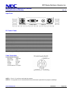
Distance Chart for popular 4:3 screens
Sc
BD
Diagonal Width Height wide - tele wide - tele
inch inch inch inch inch
33 26 20 13 - 57 3 - 12.6
60 48 36 23 87 - 104 5 14.9 - 12.4
72 58 43 28 104 - 126 6 14.9 - 12.4
84 67 50 32 122 - 147 7 14.8 - 12.4
90 72 54 35 131 - 157 8 14.8 - 12.4
100 80 60 38 145 - 175 8 14.8 - 12.3
120 96 72 46 174 - 210 10 14.8 - 12.3
150 120 90 58 219 - 263 13 14.7 - 12.3
180 144 108 69 263 - 317 15 14.7 - 12.3
200 160 120 77 292 - 352 17 14.7 - 12.3
260 208 156 100 380 - 458 22 14.7 - 12.3
300 240 180 115 439 - 529 25 14.7 - 12.3
reen Size C α
inch degree
Note:
For screen sizes not indicated on the projection table, use the formulas on page 1.