


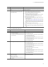
2. Troubleshooting System Failures
16
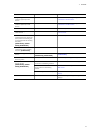
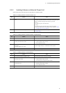
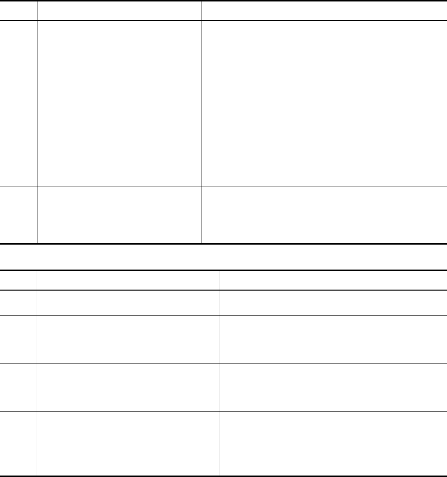
Table 2-4: Isolating Power Supply Failure
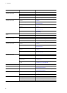
5
• ST1 LED on the system is blinking in red
• LINK LED (10GBASE-R port and
1000BASE-X port) and 1-48 LED (10/100/
1000BASE-T port) on each port of the system
are lit in orange or OFF
System or line has failed.
1. For the redundant power supply model, check the states of the power
supplies and fan unit. Replace them if they have failed.
- If ALM LED on the fan unit is lit in red, replace the fan unit.
- If ALM1 LED or ALM2 LED or the power supply is lit in red, replace
the power supply.
- If POWER LED on the power supply is off, take the action against
power failure according to "Table 2-4: Isolating Power Supply
Failure." If POWER LED is still off after the action is taken, replace
the power supply.
2. For cases other than 1 above, refer to the error message and take the
action against the failure. Execute the show logging command to
check the failure information and take the action.
>show logging | grep ERR
3. For the failure on the external power unit, refer to "2.2.2 Isolating
Failures on External Power Unit" to isolate the failure.
6 "EPU:Disconnect" is displayed for the system
management command although LEDs on the
system and external power unit are normal
Check the cable interconnecting the system and EPU. If the cable has
slipped off, restart the system as described below.
1. Power off the system.
2. Reconnect the cable that has slipped off.
3. Power off the system.
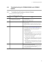
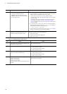
No. Failure Action
1 Power switch on the system (or power supply for the
redundant power model) is OFF
Turn on the power switch.
2 Power cable has slipped off or is loose Follow the steps below.
1. Turn off the power switch.
2. Connect the power cable correctly.
3. Turn on the power switch.
3 For the redundant power supply model, the power
supply is not securely mounted but loose
Follow the steps below.
1. Turn off the power switch.
2. Insert the power supply correctly.
3. Turn on the power switch.
4 Measured input power is out of the range below.
100VAC: 90 to 127VAC
200VAC: 180 to 254VAC
-48VDC: -40.5 to -57VDC
Note: Implement this matter only if input power can be
measured.
Contact the person in charge of the power facility and ask him/her to
take the action for input power.
No. Failure Action