


NEC Display Solutions of America, Inc.
NP100/200 Installation Guide
Ceiling Mounted and Desktop Rev 1.0
www.necdisplay.com NP100/200 Page 2 of 5
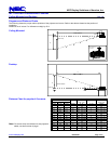
Diagrams and Distance Charts
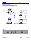
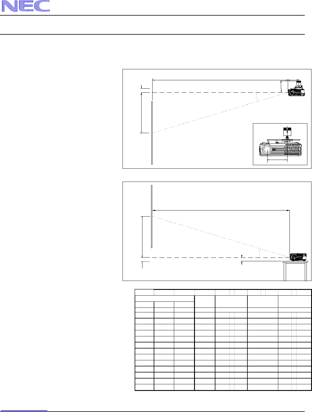
The following shows the proper relative positions of the projector and screen. Refer to the table to determine the position of
installation.
Distances are in inches. For millimeters multiply by 25.4.
B
C
Lens Ctr
Screen Ctr
Throw Distance
Screen Bottom
1.90"
C
Throw Distance
Screen Top
5.23"
5.54"
Lens Offset From
Mount Pipe
D
B
Lens Ctr
Screen Ctr
D
5.13"
Ceiling Mounted
Desktop
Diagonal Width(W) Height (H)
inches inches inches inches
30 24 18 12 N/A - 52 N/A - 12.8
60 48 36 23 94 - 103 14.0 - 12.8
67 53.6 40.2 26 104 - 115 14.0 - 12.8
72 57.6 43.2 28 112 - 124 14.0 - 12.8
84 67.2 50.4 33 131 - 144 14.0 - 12.8
90 72 54 35 140 - 155 14.0 - 12.8
100 80 60 39 156 - 172 14.0 - 12.8
120 96 72 47 187 - 206 14.0 - 12.8
150 120 90 59 234 - 258 14.0 - 12.8
180 144 108 70 281 - 310 14.0 - 12.8
210 168 126 82 327 - 361 14.0 - 12.8
240 192 144 94 374 - 413 14.0 - 12.8
270 216 162 106 421 - 464 14.0 - 12.8
19
22
24
9
11
14
16
6
7
8
8
D
α
wide - tele
d
egrees
Screen Size (4:3)
5
i
nc
h
es
3
B
C
wide - tele
i
nc
h
es
Distance Chart for popular 4:3 screens
Note: For screen sizes not indicated on the projection
tables, use the formulas on page 1.