


NEC Display Solutions of America, Inc.
VT695/700 Installation Guide
Ceiling Mounted and Desktop Rev 1.0
www.necdisplay.com VT695/700 Page 2 of 6
Diagrams and Distance Charts
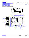
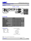
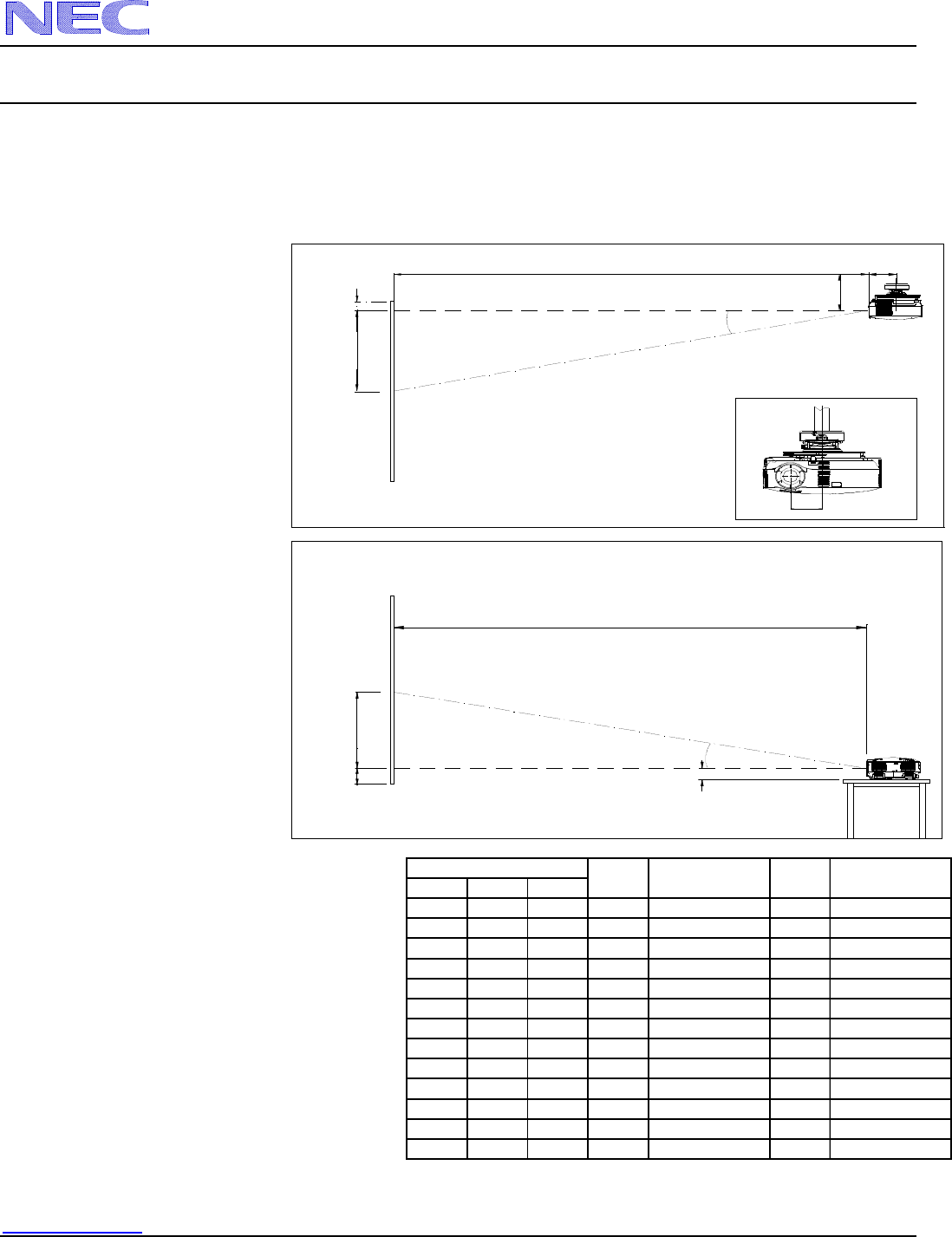
The following shows the proper relative positions of the projector and screen. Refer to the table to determine the position of
installation.
Distances are in inches. For millimeters multiply by 25.4.
Ceiling Mounted
B
C
Lens Ctr
Screen Ctr
Throw Distance
Screen Top
5.26"
5.68"
Lens Offset From
Mount Pipe
3.27"
D
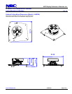
Desktop
B
C
Lens Ctr
Screen Ctr
Throw Distance
Screen Bottom
2.57"
D
Screen Size (4:3)
Diag W H
inches inches inches inches inches
30 24 18 6 -3
60 48 36 13 -5
72 57.6 43.2 15 -6
84 67.2 50.4 18 -7
90 72 54 19 -8
100806021 -9
120967226 -10
150 120 90 32 -13
180 144 108 38 -16
200 160 120 43 -17
250 200 150 53 -22
300 240 180 64 -26
B
C
wide - tele
D
α
wide - tele
inches degrees
34 - 41 10.6 - 8.9
70 - 84 10.5 - 8.7
84 - 101 10.4 - 8.7
98 - 118 10.4 - 8.7
105 - 126 10.4 - 8.7
117 - 141 10.4 - 8.7
141 - 169 10.4 - 8.7
176 - 211 10.4 - 8.7
211 - 254 10.4 - 8.7
353 - 424 10.3 - 8.6
235 - 282 10.4 - 8.7
294 - 353 10.3 - 8.6
Distance Chart for popular 4:3 screens
Note: For screen sizes not indicated on the projection
tables, use the formulas on page 1.