


11
EXAMPLES OF CONNECTIONS
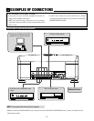
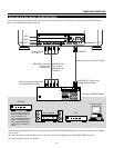
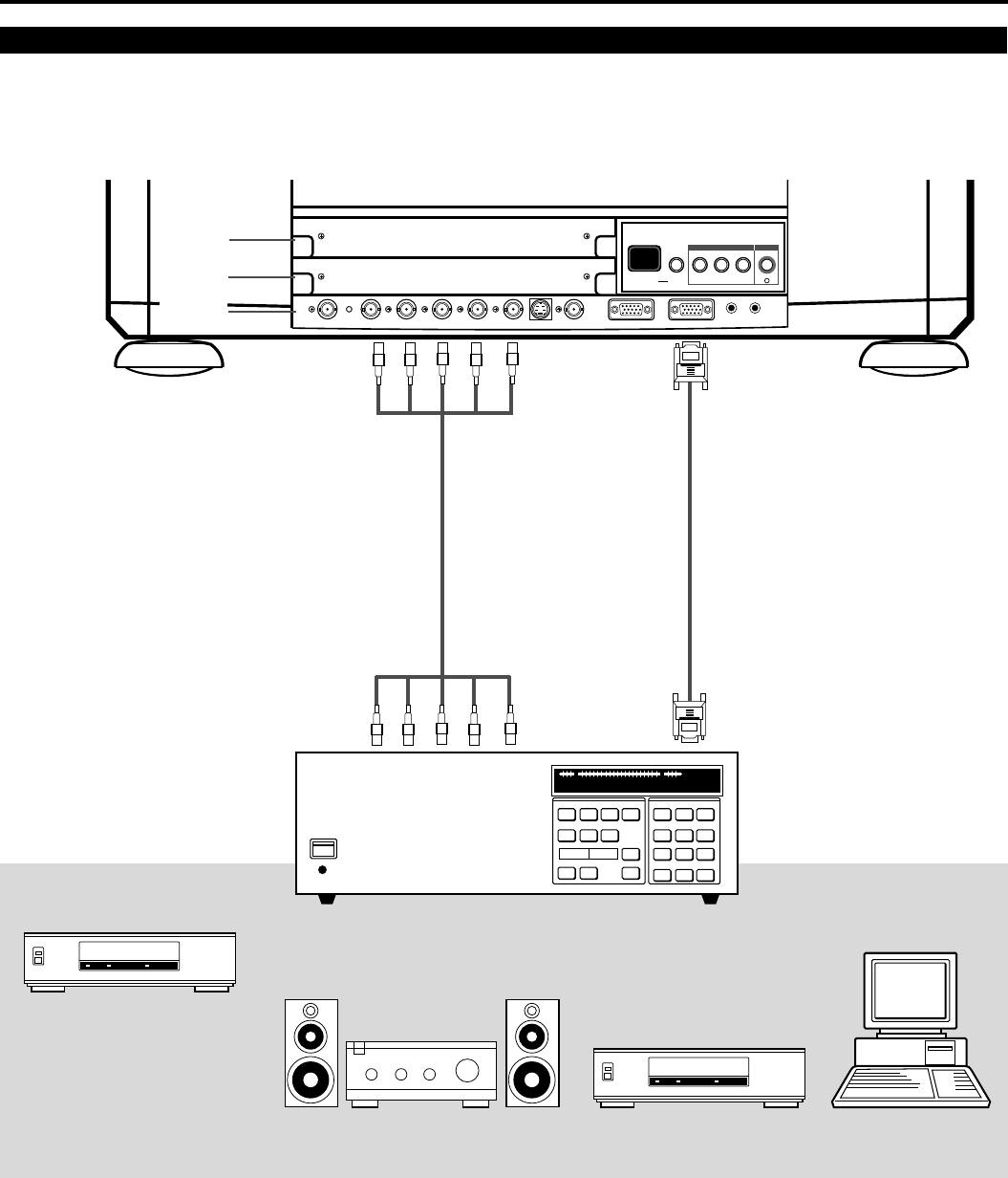
When Used with One Switcher (ISS-6020/ISS-6020G)
Up to 10 input signals can be accepted when the projector is connected to one Switcher. Using the projector with the Switcher
allows easy adjustment and signal selection.
• Make sure that the SW1 LEVEL mode is selected from the CONNECT CONDITION menu. Contact your dealer for the informa-
tion in detail.
• For more information on the Switcher, refer to the user’s manual accompanying the ISS-6020/ISS-6020G Switcher.
• All cables mentioned above are optional.
The Switcher ISS-6020/ISS-6020G
Personal computer
Audio equipment
VCR
ACAT OUT R/Cr G/Y B/Cb H/HV V S-VIDEO VIDEO OPTION REMOTE1 REMOTE2
OUT IN
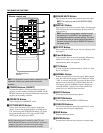
INPUT SELECT ENTERON/OFFINDICATOR
I
INPUT SELECT POWER
From R, G, B, H/V on separate H and
V. on the RGB OUTPUT module
To REMOTE1
From REMOTE 1 Terminal on the
SYSTEM CONTROL module
Optional control cable 15p-15p (CTL-6010)
5BNC-5BNC coaxial cable
(separate sync)
(recommended)
To INPUT A (RGB,
H/V,V inputs)
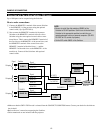
INPUT B
INPUT C
INPUT A
3BNC-3BNC cable
(sync on green)
4BNC-4BNC cable
(composite)
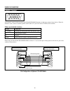
DVD Player
* To connect a COMPONENT signal
of the equipment such as DVD
player to the optional RGB input
board, the projector must
recognize the optional RGB input
board as a COMPONENT input
board. See “RGB/COMPONENT
Search Setting” of the Set-up
manual.