


3
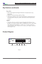
Installation Guide for 10/100/1000 Bypass Switch
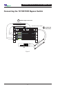
Connecting the 10/100/1000 Bypass Switch to the
Network
1. Unpack the Bypass Switch, and obtain the required cables needed to
successfully install the unit.
2. Connect Network Port A to the appropriate switch, server or router device.
This will act as your DCE Interface.
3. Connect Network Port B to the appropriate switch, server or router device.
This will act as your DTE interface.
4. Verify that the Bypass Switch Network Ports are cabled in-line between two
devices.
Connecting the 10/100/1000 Bypass Switch to the
Intrusion Prevention Device
1. Connect Monitoring Port A to the IPS sensor port A using a CAT5 RJ45
cable. This will act as your DCE Interface.
2. Connect Monitoring Port B to the IPS sensor port B using a CAT5 RJ45
cable. This will act as your DTE interface.
3. Verify that the Switch Monitoring Ports are cabled in-line between two
devices.
Cabling Guidelines
10/100 Devices:
- If connecting to Switches or Hubs, use CAT5 RJ-45 Cross-over cabling.
- If connecting to Routers or NIC cards, use CAT5 RJ-45 Straight-thru
cabling.
GigaBit Devices:
- CAT5 RJ-45 Straight-thru cabling.