


Installation Guide
Follow these quick steps to install your switch.
You can also consult the full hardware installation guide on the
NETGEAR 7000 Series Managed Switch Resource CD.
1 VERIFY THE FOLLOWING PACKAGE CONTENTS
• 7000 Series Managed Switch
• Rubber footpads for tabletop installation
• Power cord
• Null-modem console cable
• Rack-mount kit for installing the switch in the rack
• This Installation Guide
•CD ROM
• Warranty and Support Information Cards
If any item is missing or damaged, contact your place of
purchase immediately.
2 SET UP THE SWITCH
a. Prepare the site so that the mounting, access, power source,
and environmental requirements identified in the Hardware
Installation Guide published on the CD-ROM are met.
b. Install the switch.
• Installing the Switch on a Flat Surface: Stick one of the
rubber footpads that came with the switch on each of
the four concave spaces on the bottom of the switch.
• Installing the Switch in a Rack: Use the rack-mount kit
supplied with your switch.
c. Apply AC Power
When you apply power, the Power LED on the switch’s
front panel will be Yellow, as it conducts a Power On Self
Test (POST). After the switch passes the POST, the Power
LED will change to Green and the switch is functional and
ready to pass data. If the POST fails, the Power LED will
stay Yellow.
If the Power LED does not go on, check that the power
cable is plugged in correctly and that the power source is
good. If this does not resolve the problem, refer to Appendix
B, Troubleshooting, in the Hardware Installation Guide on
the CD-ROM.
d. Connect Devices to the Switch
Use Category 5 (Cat5) cable to connect devices.
SFP modules ship separately. If you need instructions on
installing an SFP module, please refer to the Hardware
Installation Guide on the CD-ROM.
3 INITIAL CONFIGURATION
To configure the IP address, you must first access the Command
Line management utility via the console interface. You can
connect to it using a VT100/ANSI terminal or a PC, Apple
Macintosh, or UNIX workstation that is directly connected to
the switch’s console port.
a. To connect a console to the switch:
– Using the null-modem cable supplied with the switch,
connect a VT100/ANSI terminal or a workstation to the
switch port labeled Console.
– If you attached a PC, Apple Macintosh, or UNIX
workstation, start a terminal-emulation program:
– Windows users can use HyperTerminal.
– Macintosh users can use ZTerm.
– UNIX users can use a terminal emulator like TIP.
b. Configure the terminal-emulation program to use the
following settings:
• Baud rate: 9,600 bps
• Data bits: 8
•Parity: none
• Stop bit: 1
• Flow control: none
These settings appear below the connector on the switch
front panel.
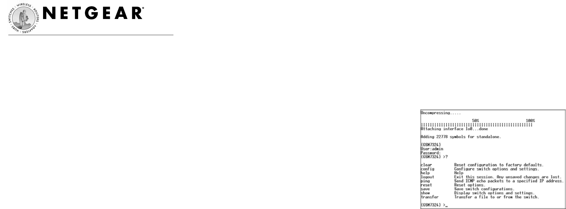
c. Press the return key, and the screen below should appear.
d. The login name is admin and there is no password assigned.
Enable an admin password to secure access to the switch
management function. After successful login, the screen
should show the (Switch Name)> prompt In this example
the prompt is (GSM7324) >. Enter show network to display
the management CPU’s IP address. The switch is shipped
using DHCP by default to receive its IP address.
7000 Series Managed Switch