


Model EN104TP/EN106TP/EN108TP Ethernet Hub Installation Guide
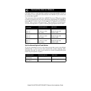
LEDs
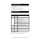
The table below describes the activity of the LEDs.
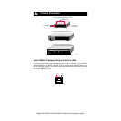
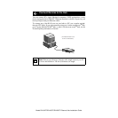
Normal/Uplink Push Button
The Normal/Uplink push button allows you to select Normal (MDI-X) wiring
for direct PC connection. The push button also allows you to select Uplink
(MDI) wiring for connection to a hub or a switch through port 4 on the
Model
EN104
TP
hub
, port 6 on the
Model EN106
TP
hub, or port 8 on the
Model EN108
TP
hub. This uplink configuration eliminates the need to use a crossover cable. The
other 10BASE-T ports are permanently configured for normal wiring for
connection to a PC.
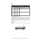
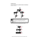
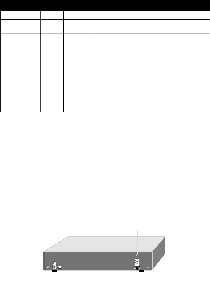
Rear Panel
The rear panel of the hub has a ground clip and a receptacle for the power
adapter.
Label
Color Activity Description
Pwr (Power) Green On Power is supplied to the hub.
Col (collision) Amber Blinking Data collision is occurring on the network. Note
that occasional collisions are normal.
Link
(on the top
right corner of
each vista
10BASE-T
port)
Green On The link between this port and the connected
device is good.
Rx
(on the top
right corner of
each vista
10BASE-T
port)
Green Blinking There is incoming data on the port.
8730FA
5Vdc 800mA
Power
receptacle
— +