


11
XS712T Smart Switch
Port LEDs
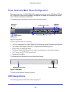
The following table describes the RJ-45 and combo SFP+ port LED designations. Each
RJ-45 port has two LEDs.
Each SFP+ port has its own indication LEDs.
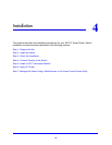
Table 1. Port LEDs
LED Designation
Link/Speed/ACT LED mode for
copper ports 1 to 12
• Off. No link established.
• Sol
id green (left side). A valid 10-Gbps link is established.
• Blink
ing green (left side). The port is transmitting or receiving
packets at 10 Gbps.
• Sol
id yellow (right side) . A valid 100/1000-Mbps link is established.
• Blin
king yellow (right side). The port is transmitting or receiving
packets at 100/1000 Mbps.
Link/ACT LED for SFP+ ports
11 and 12
• Off . No SFP+ module link is established.
• Sol
id green (left side) . A valid 10-Gbps link is established.
• Blin
king green (left side). The port is transmitting or receiving
packets at 10 Gbps.
• Sol
id yellow (right side) . A valid 1000-Mbps link is established on
the port.
• Blin
king yellow (right side) . The port is transmitting or receiving
packets at 1000 Mbps.
System LEDs
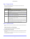
Table 2. System LEDs
LED Designation
Power • So
lid green . The device is powered on; runtime code is operating.
• So
lid yellow . The device is booting up.
• Off . Power is not supplied to the device.
Fan • So
lid yellow . The fan has experienced a failure.
• Off . The fan is operating normally.
The following table describes the system LED designations.
Device Hardware Interfaces
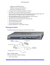
The following sections describe the hardware interfaces on the device.