Broadband Without Boundaries®
1.
Unpack your wireless Router and decide where you want to place it. Things to consider:
• Place it in a spot that is easily accessible for you.
• You can lay it flat or mount on the wall.
• Keep the cords away from other electrical devices that may interfere with the operation of your Router.
• Be sure that the antenna is in the vertical position.
2.
Connect the power supply to the power jack on the Router back panel, and the other end
into an outlet.
3.
Turn the power on by flipping the Off/On switch to the ‘On’ position.
4.
Insert one end of the yellow RJ-45 Ethernet cable into one of the ports labeled ‘Ethernet’ on
the Router, and the other end into your PC’s Ethernet port.
5.
Insert one end of the gray RJ-11 cable into the port labeled ‘DSL’ on the Router, and the other
end into your DSL jack.
Wait for the DSL Sync light on the front of the Router to turn solid green. This could take up to two minutes.
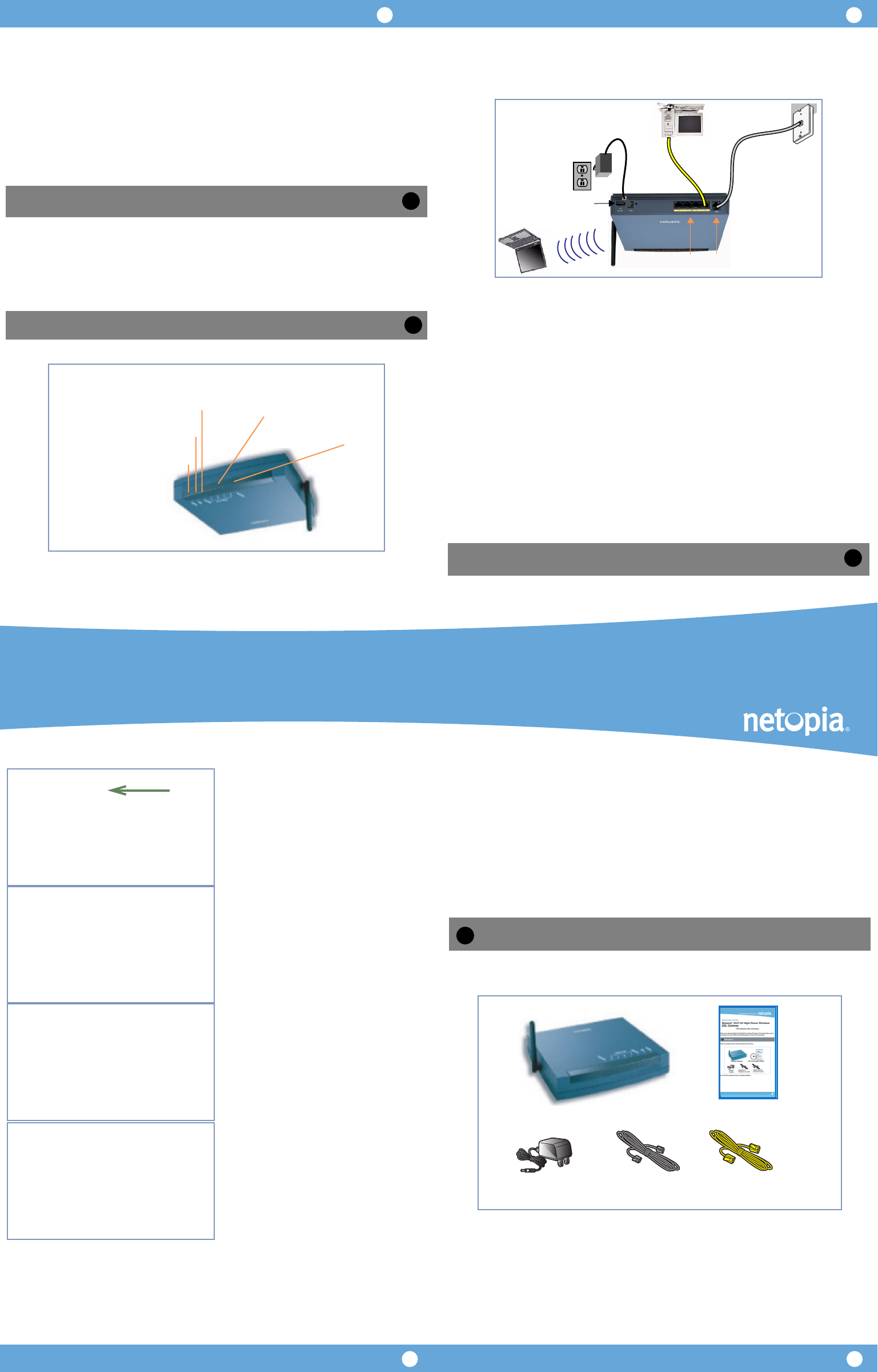
When all of your connections are made, your network may look like this.
When all of your connections are made, the status LEDs on the front of your Netopia Router will light,
according to the following diagram:
Netopia Routers serve Dynamically-assigned IP addresses by default. Be sure to configure each computer
connected to your Netopia Router to accept a Dynamically-assigned IP address, commonly referred to as
DHCP.
If you need instructions, refer to your computer’s operating system documentation for information about
DHCP configuration.
Your service provider will supply you with several parameter values. Access the configuration screens as follows:
Run a Telnet application from the computer on the same network as the Router.
• Windows users click on the
Start
menu, select
Run
, and in the resulting entry box, type
“
telnet 192.168.1.1
" (without the quotes).
• Macintosh OS X users launch the
Terminal
application, either from the Dock or from the Utilities folder, and
type “
telnet 192.168.1.1
" (without the quotes).
The Telnet window displays the
Main Menu
.
(continued on next page) -->
Set up your Router
2
DC Power
Rear View
Ethernet
Ports
Power Switch
DSL Port
Configure Your PCs for DHCP
Configure Your Netopia Router
Power -
Ethernet 1, 2, 3, 4 -
Flashes green when there is
activity on the LAN.
Front View
Solid green when connected.
Green when power is on.
Wireless -
Flashes green when there is
activity on the wireless LAN.
Solid green when Internet
connection is established
DSL -
Internet -
Solid green when Router is connected.
Flashes green when transmitting or
receiving data on the WAN port.
3
4
14
32
In the Telnet screens, move from field to field with the
arrow keys. Select items with the
Return
key, and tog-
gle items with the
Tab
key followed by
Return
.
Select
Easy Setup
and press
Return
.
The
ADSL Line Configuration
screen appears.
Your service provider must provide appropriate settings
for this screen.
Make any changes that your service provider requires or
simply accept the defaults. Select
NEXT SCREEN
and
press
Return
.
The
Connection Profile 1: Easy Setup Profile
screen
appears.
Your service provider must provide appropriate settings
for this screen.
Make any changes that your service provider requires or
simply accept the defaults. Select
NEXT SCREEN
and
press
Return
.
The
IP Easy Setup
screen appears.
Your service provider must provide appropriate settings
for this screen.
Make any changes that your service provider requires or
simply accept the defaults. Select
NEXT SCREEN
and
press
Return
.
(continued on inside pages)
Quickstart Guide
Netopia
®
3347-02-ENT and 3357-02-ENT
Extreme Wireless DSL Router
4-Port Ethernet, 802.11g Wireless
Thank you for selecting the Netopia 3347-02-ENT or 3357-02-ENT Extreme Wireless DSL Router. This guide will
help you set up and configure your network. [FAQs and Troubleshooting Tips are located on the inside pages.]
Check your package contents. It should contain the items shown here:
If you don’t have everything, contact your supplier immediately.
Netopia 3347-02 v8.7.0
Easy Setup...
WAN Configuration...
System Configuration...
Utilities & Diagnostics...
Statistics & Logs...
Quick Menus...
Quick View...
You always start from this main screen.
ADSL Line Configuration
Trellis Coding Enabled: On
Fast Retrain Enabled: On
Data Link Encapsulation... RFC1483
Annex Modes enabled: Off
Data Circuit VPI (0-255): 8
Data Circuit VCI (32-65535): 35
PREVIOUS SCREEN NEXT SCREEN
Connection Profile 1: Easy Setup Profile
Underlying Encapsulation... None
RFC1483 Mode... Bridged 1483
Address Translation Enabled: Yes
IP Addressing... Numbered
Local WAN IP Address: 0.0.0.0
Local WAN IP Mask: 0.0.0.0
PREVIOUS SCREEN NEXT SCREEN
Enter basic information about your WAN connection with this screen.
IP Easy Setup
Ethernet IP Address: 192.168.1.1
Ethernet Subnet Mask: 255.255.255.0
Domain Name: isp.com
Primary Domain Name Server: 0.0.0.0
Secondary Domain Name Server: 0.0.0.0
Default IP Gateway: 0.0.0.0
IP Address Serving: On
Number of Client IP Addresses: 100
1st Client Address: 192.168.1.100
PREVIOUS SCREEN NEXT SCREEN
Enter an IP address in decimal and dot form (xxx.xxx.xxx.xxx).
Set up the basic IP & IPX attributes of your Netopia in this screen.
Checklist
1
Netopia Router
Quickstart Guide
Power
Supply
Gray RJ-11
Telephone Cable
Yellow RJ-45
Ethernet Cable
Netopia Part Number:
6180205-00-01
Copyright 2007, Netopia, Inc. Netopia, the Netopia logo, and Broadband Without Boundaries are registered trademarks belonging to Netopia, Inc., registered
U.S. Patent and Trademark Office. All other trademarks are the property of their respective owners. All rights reserved.


