Netopia
®
4686-XL Broadband VPN Router with Back-up
High-performance
Speed and performance with
hardware-based VPN acceleration
and an integrated Ethernet switch
Mission Critical
Integrated dial back-up improves
uptime and delivers high-
availability
Enterprise-class
Robust routing, security, and
management features optimized
for enterprise applications
Netopia 4686-XL
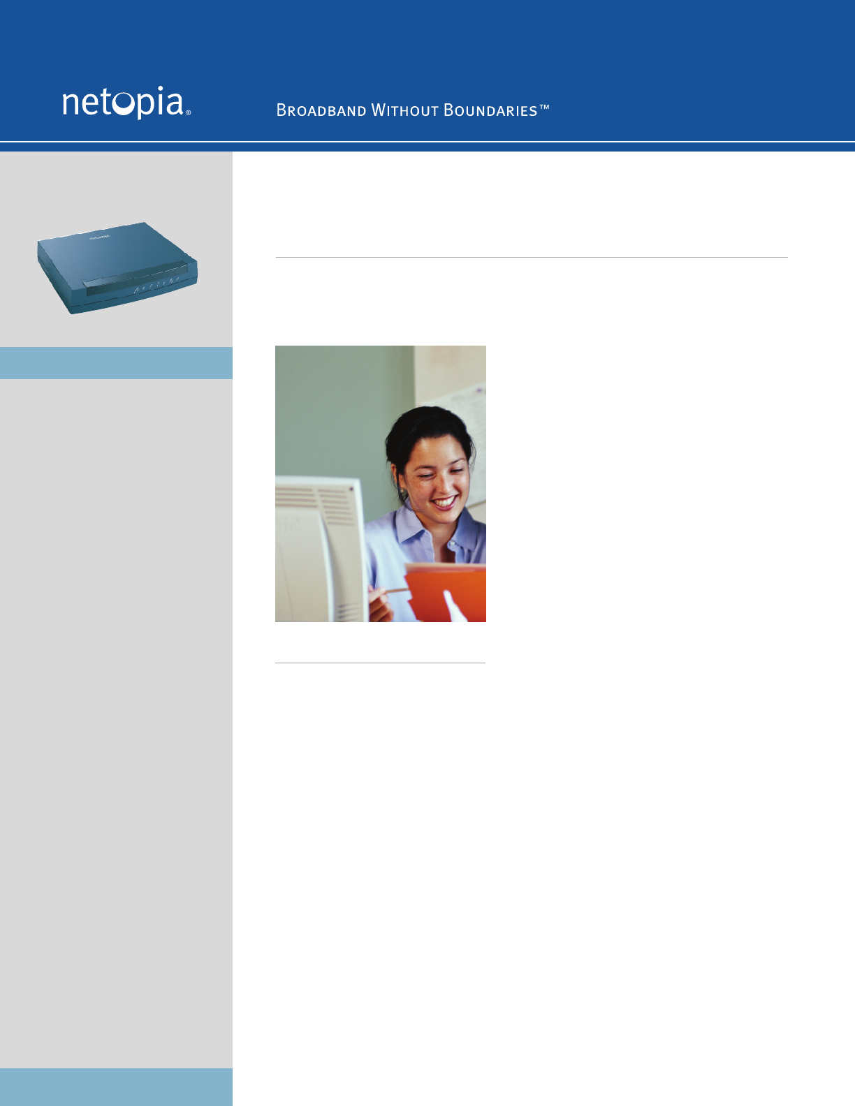
Speed, performance, and enterprise-class features
for the demanding business user
The Netopia 4686-XL Broadband VPN Router is a
high-performance VPN router with dial back-up
capabilities. Designed for enterprise users and
managed service providers, the Netopia 4686-XL
enables wire-speed VPN networking and stateful
firewall security, while increasing uptime with its
integrated V.92 modem. The 4686-XL connects
directly to any external broadband modem, such as
DSL or cable modems, and is ideal for retail and
branch office applications.
The Netopia 4686-XL helps enterprises save time
and money with its high-availability features.
Configured for dial back-up scenarios, the integrated
V.92 modem automatically dials a pre-configured
back-up connection if the primary WAN connection is
lost. Alternatively, the integrated modem may be
used for out-of-band remote management by IT
departments, VARs, or service providers.
With integrated hardware acceleration, the Netopia
4686-XL powers wire-speed VPN applications for
retail, branch offices, and enterprise teleworkers.
The device comes standard with a wide-range of
routing, security, and management features
optimized for enterprise applications. Unlike
competitive solutions that require expensive and
cumbersome firmware upgrades, the 4686-XL is
deployment ready for applications requiring wire-
speed VPNs, stateful firewall security, and
enterprise-class remote management. The rich
security feature set and high-performance hardware
features eliminate the need an additional firewall or
VPN security appliance.
For the enterprise user or managed service provider,
the Netopia 4686-XL is an ideal solution for secure,
reliable, and high-performance networking.
Netopia Broadband Gateways
Only Netopia offers affordable Broadband Gateways
for every connection type – from DSL to T1. Perfect
for homes, home offices, teleworkers, small
businesses and corporate branch offices, Netopia
Broadband Gateways bring high speed broadband
Internet access to every computer. Built-in security
protects data, applications and gateways without the
need to purchase separate software or hardware.
Advanced features support growth while protecting
your investment. Quick setup, comprehensive
management and high reliability make Netopia both
powerful and easy to use.
High-performance Broadband Router with integrated VPN acceleration
and dial back-up


