


6
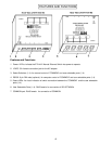
Plug-in and Boot Up
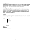
1. Connect the AC adapter power connector to the 12VDC port on the ETH-4X1 Manual Ethernet Switch.
Make sure the power connector is properly inserted. (See Fig. 3.)
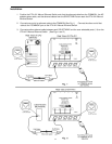
2. Plug the AC adapter into a power outlet. The “Power” LED on the ETH-4X1 Manual Ethernet Switch should
illuminate indicating that a proper power connection has been made. Status LED "1" should also illuminate
indicating a connection between the "COMMON" port and user selectable port 1.
3. Power up the COMMON and SELECTABLE device(s). The COMMON device should react as if it were
directly connected to the SELECTABLE device plugged into user selectable port 1.
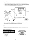
RS232
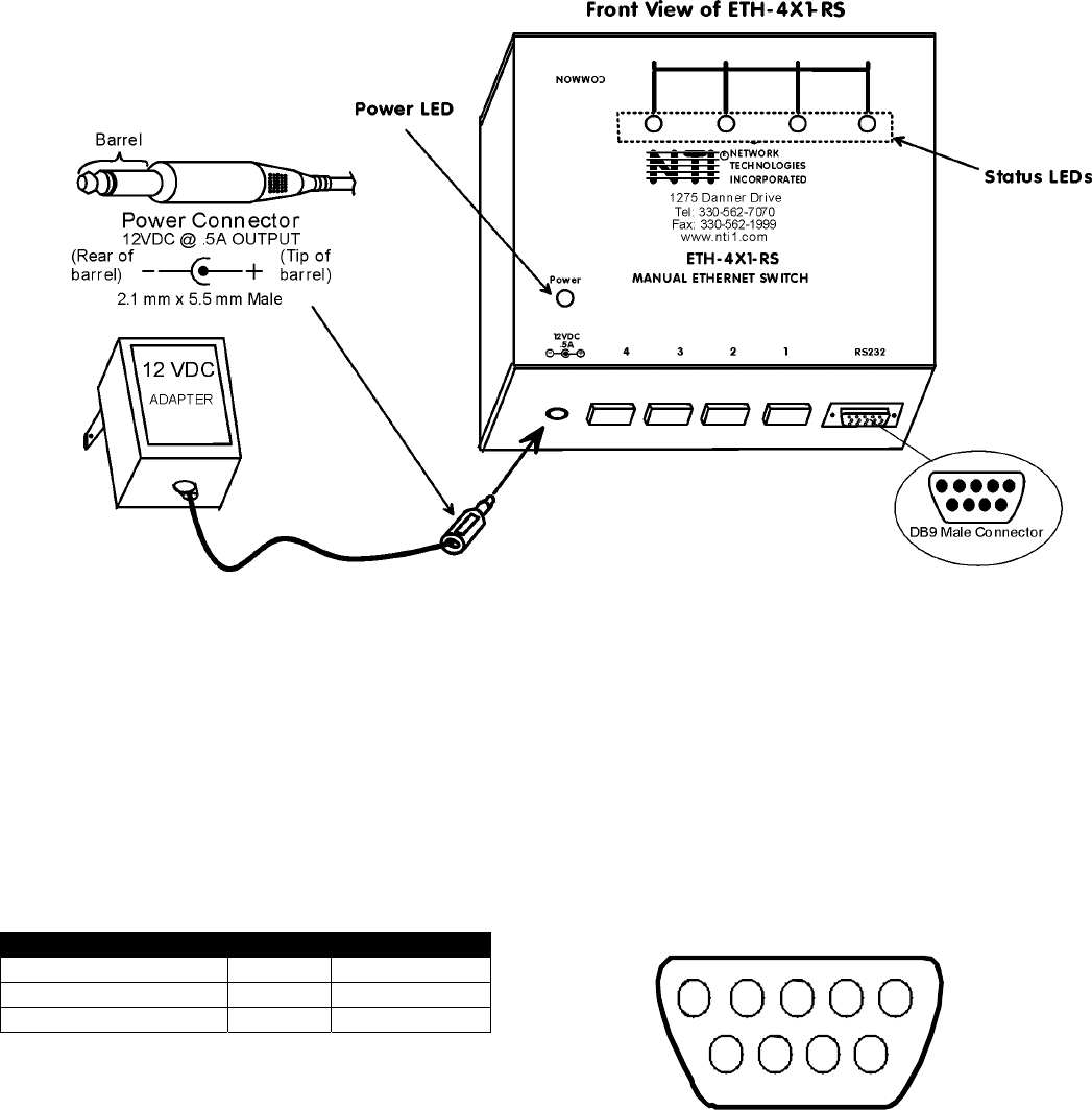
To use the RS232 port (optional) , connect a crossed female serial cable from a CPU serial port to the DB9 pin
male RS232 port on the ETH-4X1-RS Manual Ethernet Switch. Connections are as follows:
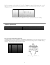
Connector: Standard 9 pin serial, male
Pins at ETH-4x1-RS Signal Pins at CPU
2 RxD 3
3 TxD 2
5 GND 5
RS-232 setup parameters:
• 9600 baud
• 8 bit data
• 1 stop bit
• no parity
• no flow control
Fig. 3
1
Mating Face of Male DB9
23
4
5
6
7
89