


4
Installation
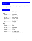
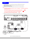
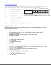
1. Turn OFF power to all video sources (inputs) that will be connected to the VEEMUX-A before connecting or
disconnecting any cables.
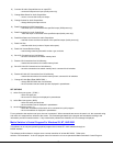
2. For each video source, connect a VEXT-xx-MM cable from the video port of the source to a video input
(VIDEO-1) of the VEEMUX-A (see Fig. 1).
3. Repeat step 2 for remaining video sources.
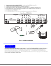
4. For each audio source, connect a SA-xx-MM cable from the audio source to the port labeled AUDIO IN 1.
Notes:
The audio port on a CPU may be marked "line out", "spkr", or "headphones".
If all 3 jacks are available, use
the jack marked "line out".
The "line out" jack is typically lime green and may be marked with this symbol
The "spkr" jack is typically orange, and may be marked with this symbol
The "headphones" jack may be marked with this symbol
5. Repeat step 4 for remaining audio sources, connecting them to any remaining AUDIO IN ports.
Figure 1- Install Audio and Video Source Cables
Installation
M O N IT O R 1
M O N IT O R 2
M O N IT O R 3
M O N IT O R 4
V ID E O 1
V ID E O 2
V ID E O 3
V ID E O 4
V ID E O 5
V ID E O 6
V ID E O 7
V ID E O 8
R
S
2
3
2
M O N IT O R 5
M O N IT O R 6
M O N IT O R 7
M O N IT O R 8
N T I
N E T W O R K
T E C H N O L O G IE S
IN C O R P O R A T E D
T e l: 3 3 0 -5 6 2 -7 0 7 0
F a x :3 3 0 -5 6 2 -1 9 9 9
1 2 7 5 D a n n e r D r
A u r o r a , O H 4 4 2 0 2
w w w .n t i1 .c o m
1
2
3
4
5
6
7
8
1
2
3
4
5
6
7
8
A U D I O IN (C P U )
A U D I O O U T ( U S E R )
R e a r V i e w o f V E E M U X - A
1 5 H D M a l e
V i d e o C o n n e c t o r
1 5 H D F e m a l e
V i d e o C o n n e c t o r
1 5 H D F e m a l e
V i d e o C o n n e c t o r
V i d e o P o r t
R e a r V i e w o f a C P U
V E X T -
x x
- M M
3 . 5 m m S t e r e o
P l u g
3 . 5 m m S t e r e o
P l u g
3 . 5 m m S t e r e o
J a c k
S A - x x - M M
A u d i o P o r t
l i n e
o u t
O N E W I L L B E M A R K E D " l i n e
o u t " ," s p k r " , " h e a d p h o n e s "
O R W I T H T H I S S Y M B O L