


11/11
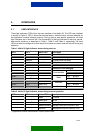
Table 3. Nokia 30 light indicator states in special situations.
LED 1 LED 2 Status LED Description
Green/Red blink Green/Red blink Green/Red blink Insert SIM card
Red blink Red blink Red blink Failure, contact service
Yellow Yellow Yellow Initialising
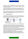
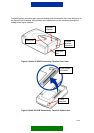
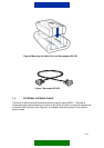
5.2 M2M SYSTEM CONNECTOR INTERFACE
The preferable interface between the Nokia 30 and the application is the M2M system
connector. The M2M system connector supports CORBA messaging, power input/output,
RS232 at 3 V level, Digital Audio Interface (DAI) and analog audio interface, and remote
input/output control. The M2M system connector is shown in Figure 3.
The M2M system connector offers an open interface for application developers and effective
and reliable methods for controlling the terminal and the application.
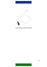
5.3 POWER INTERFACE
The Nokia 30 has a DC connector for the Nokia ACW-5A power supply. The power interface
is shown in Figure 3.
• Input voltage range: 6.2 Vdc – 14.0 Vdc
The M2M system connector provides regulated voltage for the application. Alternatively, the
application module can supply the terminal with a wide voltage range.
• DC input voltage range: 4.75 V – 15.0 V
Nokia 30 has a regulated switch able power output for customer application.
• DC output voltage: 3.6 V DC
• DC output current: 300 mA
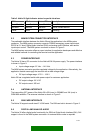
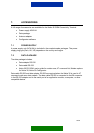
5.4 ANTENNA INTERFACE
The transmitting (RF) power of the Nokia 30 is 2W (max) in GSM900 and 1W (max) in
GSM1800 networks. The antenna interface is shown in Figure 2.
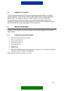
5.5 SIM CARD INTERFACE
The Nokia 30 supports small-sized 3 V SIM cards. The SIM card slot is shown in Figure 2.
5.6 DIGITAL AND ANALOG AUDIO
The Nokia 30 offers digital audio functionality for GSM via Digital Audio Interface (DAI). DAI
support is found in the M2M system connector. An external audio codec is required.