


DeviceNet Physical Layer and Media
Adept SmartController User’s Guide, Rev. E 117
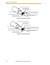
Connecting DeviceNet Hardware to the Adept DeviceNet Scanner
To connect DeviceNet components to the Adept DeviceNet Scanner, connect a dropline to
the female Micro-style 12 mm thread DIN connector on the front of the SmartController.
Then you must configure the DeviceNet Scanner correctly using the
CONFIG_C
program. See the Instructions for Adept Utility Programs for information on using
CONFIG_C.
See the DEVICENET monitor command in the V+ Operating System Reference Guide for
detailed information about the DeviceNet software setup in V
+
.
NOTE: Adept does not supply 24V on the SmartController to power the
DeviceNet bus. A separate power supply is required to power the
components on the DeviceNet bus.
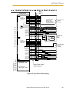
B.4 DeviceNet Physical Layer and Media
The DeviceNet physical layer and media specifications are published in the ODVA
manual, chapter 9, volume 1. It describes possible topologies and components of the
physical layer of the DeviceNet.
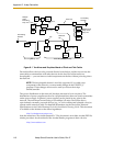
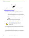
Figure B-1 shows several possible topologies. The DeviceNet specifications also specify
system grounding, mixing of thick and thin cable media, termination, and power
distribution.
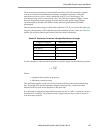
The basic topology is the trunkline-dropline topology. This topology uses separate
twisted-pair buses for the distribution of signals and power. The specifications allow
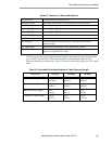
trunklines and droplines made of thick or thin cable. The baud rate, maximum distance
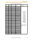
from end-to-end of the network, and cable size are dependent on each other. See Tab le B-2
on page 119 for further details.
WARNING: The DeviceNet specification requires that the
CAN_H and CAN_L signal lines tolerate voltages up to
18V. Since the supply voltage exceeds 18V, improperly
wiring the supply voltage to these signal lines may cause
permanent damage.