


Logic Voltage Check-out Procedure{ XE "Adjustment:Multivolt logic
power supplies" }
The outputs of the power supplies { XE "Power supplies, multivolt logic:Adjustment" } { XE
"Power supplies, multivolt logic:Voltage checkout procedure" }{ XE "Logic power supplies" \t
"See power supplies, multivolt logic" }are read at their most critical point—the input to the
Camera Controller board, the Solenoid Clutch Activation board, and the Top LED Mother
board.
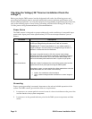
1. Turn on the scanner power switch.
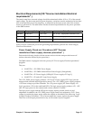
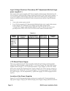
2. Use a DVM to measure { XE "Measurement:Multivolt logic power supply" }the outputs
to the voltages { XE "Checkout:Logic voltages" }{ XE "Logic voltages" }{ XE
"Voltage:Power supply, multivolt logic" }listed in Table 2-4. Be sure to connect your
ground probe to TPG1, TPG2, TPG3, or TPG4 on the Camera Controller board.
Table 2- 4
Nominal
Voltage
Camera
Controller Pin
Location
Solenoid Clutch
Activation Board
(SCAB) Pin Location
Top LED
Mother Board
Pin Location
Acceptable
Range
+5V{ XE
"Logic power
supply" \t
"See power
supply, +5V
logic"
}
J5 - 3 +4/95 to +5.20V DC
-15V J5 - 1 -15.0 to -15.20V DC
+15V J5 - 2 +15.0 to -15.20V DC
Ground TPG1, TPG2, TPG3,
TPG4
+12.5V J9 - 4 +12.5 to +13V
+V Boost J9 - 7 +12 to +16V
+5V J3 - 1 +5 to +5.5V
+12V Boost Power Supply
There are no adjustments{ XE "Power supplies, multivolt logic:Voltage outside specified
range" }{ XE "Power supplies, multivolt logic" \t "See Power supply, 15V logic" }{ XE "Power
supplies, multivolt logic" \t "See Checkout procedures - logic voltages" } to the +12V, 200W
boost power supply{ XE "Checkout:Power supply voltages" { XE "Power supply voltages" }}.
If its output is not +12.5V{ XE "+12.5V power supply" \t "See Power supply, +15V" } to 16V{
XE "Power supply, +15V:No adjustments" }, replace the supply{ XE "Power supply:No field
repair" }.
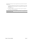
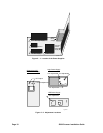
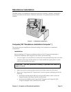
Location of the Power Supplies
Figures 2-1 and 2-2 illustrate the location of the power supplies { XE "Checkout:Multivolt
logic power supply voltage" }{ XE "Multivolt logic power supply voltage" }and the location of
Page 16 5000i Scanner Installation Guide