


Managing cables for the Ethernet Routing Switch 8000 Series chassis 93
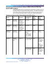
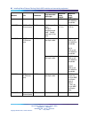
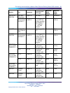
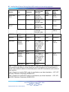
Module Port
Connector
Recommended
cable type
Minimum
cable
length
Maximum
cable
length
Note 4: Depends on installed Gigabit Ethernet transceiver model; for specifications, see Nortel
Installation — SFP, XFP, and GBIC Hardware Components (NN46225-301).
Note 5: Depends on installed XFP model; for specifications, see Nortel Installation — SFP, XFP,
and GBIC Hardware Components (NN46225-301).
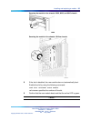
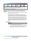
Managing cables for the Ethernet Routing Switch 8000 Series
chassis
Manage the cables for the Ethernet Routing Switch 8000 Series chassis to
keep them fastened and out of the way.
The Ethernet Routing Switch 8000 Series chassis ship with cable
management brackets. The cable management brackets keep groups of
cable clusters fastened and out of the way, but accessible for maintenance.
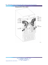
To facilitate card installation and removal, bundle the cables for each slot.
Connect, label, and bundle the cables for each module together, then use
Velcro straps or sheet fiber wrapped around the cables to organize them
along the entire cable path before you connect cables to another module.
Secure the Velcro straps or sheet fiber to brackets with lacing cord or tie
wrap.
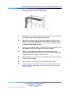
Procedure steps
Step Action
1
Connect the appropriate cable to the module.
2
Route the cable up to the appropriate cable management bracket
and channel ("Managing cables: 8010co chassis" (page 94) and
"Managing cables: 8010, 8006, 8003 chassis" (page 95)).
Nortel Metro Ethernet Routing Switch 8600
Installation — Modules
NN46220-306 02.02 Standard
4.2 7 July 2008
Copyright © 2005-2007, Nortel Networks
.