


Getting Started with the Contivity Extranet Switch 1500 Series
3-10
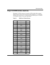
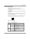
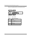
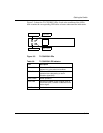
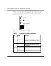
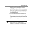
Figure 3-4 shows the Single V.35 LEDs. Look at the condition of the LEDs, then
examine the corresponding LED tables to better understand the indications.
Figure 3-4. Single V.35 LEDs
Table 3-5. Single V.35 LED Indicators
LED Description
LED1 Power is on to the adapter and the onboard
microcode is loaded.
LED2 The signals CDC and DSR are on between the
DSU and the adapter. LED2 detects receive
link status.
LED3 Cable is detected.
LED4 No external transmit clock source is available.
LED 4, Red
LED 3, Green
LED 1, Yellow
LED 2, Blue