


Site requirements 27
• 8005DC
• 8005DI DC,
The PoE feature requires the following components:
• Ethernet Routing Switch 8306 or 8310 chassis with PoE backplane
• Ethernet Routing Switch 8301AC or 8302AC power supply
•
Ethernet Routing Switch 8393SF/CPU or 8394SF/CPU module
and a choice of either of the following:
•
Ethernet Routing Switch 8348TX-PWR module
• Ethernet Routing Switch 8348GTX-PWR module
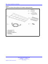
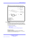
Fan trays
Table 1 "Number of fan trays installed for each chassis" (page 27) lists
the number of fan trays for the Ethernet Routing Switch 8310 and 8306
chassis.
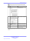
Table 1
Number of fan trays installed for each chassis
Chassis
Fan tray
8310
Two fan trays; each fan tray contains eight high-capacity fans.
8306
One fan tray containing six high-capacity fans.
A control/monitor circuit board in the fan tray reports temperature and
fan operating status to the network management software. A green light
emitting diode (LED) indicates that the fan tray is operating correctly. For
information about installing the fan, see Nortel Ethernet Routing Switch
8300 Installation — Fan Tray, (NN46200-302).
Site requirements
Ensure that the installation site meets the space, electrical, and
environmental requirements listed in this section. For more information
see, “Technical specifications” (page 55).
Space requirements
The installation site must provide sufficient free space around the chassis
to ensure proper ventilation and access for servicing.
Nortel Ethernet Routing Switch 8300
Installation — Chassis
NN46200-309 01.01 Standard
16 June 2008
Copyright © 2008 Nortel Networks
.