


16 • Jumpers and Connectors
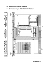
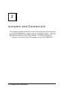
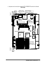
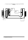
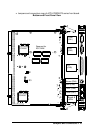
2.1 Jumpers, Connectors and LED Indicators on the
cPCI-6760DK/P5
The jumpers on the cPCI-6760DK/P5 CPU board allow you to configure your
CPU module according to the needs of your applications. If you have doubts
about the best jumper configuration for your needs, contact your dealer or
sales representative.
The connectors on the cPCI-6760DK/P5 CPU board allows you to connect
devices such as keyboard, mouse, VGA, COM port, Ethernet etc.
The LED indicators on the cPCI-6760DK/P5 front board show you the
information regarding to your system’s status.
The following information lists the jumpers, connectors and LEDs on the
cPCI-6760DK/P5 CPU board and their respective functions.
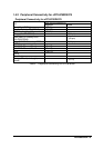
Jumper Setting Information for cPCI-6760DK/P5 Front Board
2.1.1 JP1 on cPCI-6760DK/P5 ..........................................................17
Connector Pin Assignments Information for cPCI-6760DK/P5
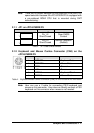
2.1.2 Keyboard and Mouse Combo Connector (CN4) on
cPCI-6760DK/P5 ......................................................................17
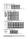
2.1.3 Ethernet Connectors (CN6, 7) ..................................................18
2.1.4 Serial Port COM1 Connector (CN1)..........................................18
2.1.5 VGA Connector (CN3)..............................................................18
2.1.6 USB (Port A) Connector (CN5).................................................18
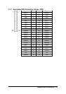
2.1.7 Secondary IDE Connectors (44-pin, CN2)...............................19
2.1.8 Primary IDE Interface (40-pin, CN11).......................................20
2.1.9 Parallel Port Connector on DB-6760J3 (CN9)..........................21
2.1.10 FDD Interface (34-pin, CN10)...................................................21
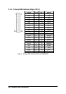
2.1.11 Ping header P3 Pin Assignments .............................................22
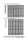
2.1.11 CompactPCI J1 Pin Assignments.............................................23
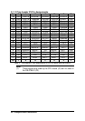
2.1.12 compactPCI J2 Pin Assignments..............................................24
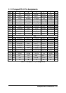
2.1.13 compactPCI J4 Pin Assignments..............................................25
2.1.14 compactPCI J5 Pin Assignments..............................................26
LED and Switch Setting Information for cPCI-6760DK/P5 Front Board
2.1.15 LAN Port Indicators (Integrated in LAN1 (CN6) and LAN2
(CN7)) ..................................................................................27
2.1.16 IDE Activity LED Indication.......................................................28
2.1.17 Power LED Indication ...............................................................28
2.1.18 WDT LED Indication .................................................................28