


2-16
MS-7374 Mainboard
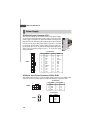
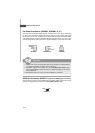
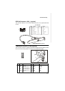
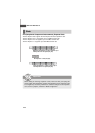
PIN SIGNAL PIN SIGNAL
1 VCC 2 VCC
3 USB0- 4 USB1-
5 USB0+ 6 USB1+
7 GND 8 GND
9 Key (no pin) 10 NC
Pin Definition
Important
Note that the pins of VCC and GND must be connected correctly to avoid
possible damage.
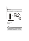
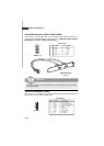
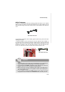
Front USB Connector: JUSB1/ JUSB2/ JUSB3
This connector, compliant with Intel
®
I/O Connectivity Design Guide, is ideal for con-
necting high-speed USB interface peripherals such as USB HDD, digital cameras,
MP3 players, printers, modems and the like.
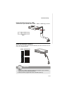
JUSB1 / 2/ 3
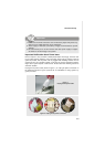
USB 2.0 Bracket
(optional)
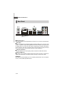
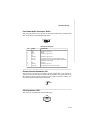
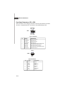
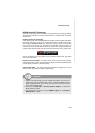
Serial Port Connector: JCOM1
This connector is a 16550A high speed communication port that sends/receives 16
bytes FIFOs. You can attach a serial device.
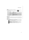
PIN SIGNAL DESCRIPTION
1 DCD Data Carry Detect
2 SIN Serial In or Receive Data
3 SOUT Serial Out or Transmit Data
4 DTR Data Terminal Ready
5 GND Ground
6 DSR Data Set Ready
7 RTS Request To Send
8 CTS Clear To Send
9 RI Ring Indicate
Pin Definition
JCOM1
2
9
1
12
910