


PCA9665_2 © NXP B.V. 2006. All rights reserved.
Product data sheet Rev. 02 — 7 December 2006 78 of 91
NXP Semiconductors
PCA9665
Fm+ parallel bus to I
2
C-bus controller
14. Test information
Test data are given in Table 52.
R
L
= load resistance.
C
L
= load capacitance includes jig and probe capacitance.
R
T
= termination resistance should be equal to the output impedance Z
O
of the pulse
generators.
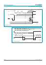
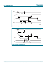
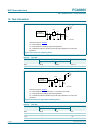
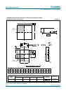
Fig 43. Test circuitry for switching times
Table 52. Test data
Test Load S1
C
L
R
L
t
d(DV)
50 pF 500 Ω V
DD
× 2
t
d(QZ)
50 pF 500 Ω open
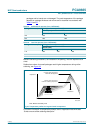
Test data are given in Table 53.
R
L
= load resistance. R
L
for SDA and SCL > 1 kΩ (3 mA or less current).
C
L
= load capacitance includes jig and probe capacitance.
R
T
= termination resistance should be equal to the output impedance Z
O
of the pulse
generators.
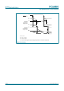
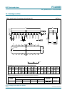
Fig 44. Test circuitry for open-drain switching times
Table 53. Test data
Test Load S1
C
L
R
L
t
d(DV)
50 pF 1 kΩ V
DD
t
d(QZ)
50 pF 1 kΩ V
DD
t
as(int)
50 pF 1 kΩ V
DD
t
das(int)
50 pF 1 kΩ V
DD
PULSE
GENERATOR
V
O
C
L
50 pF
R
L
500 Ω
002aac694
R
T
V
I
V
DD
DUT
R
L
500 Ω
V
DD
× 2
open
V
SS
PULSE
GENERATOR
V
O
C
L
50 pF
R
L
1 kΩ
002aac695
R
T
V
I
V
DD
DUT
V
DD
open
V
SS