


outboard and I/O
Mounting Location
Guidelines
CAUTION: Do not mount in line with or near water intake or
discharge openings or behind strakes, struts, fittings, or hull
irregularities that will disturb the water flow.
• The water flowing under the hull must be smooth with a
minimum of bubbles and turbulence (especially at high speeds).
• The transducer must be continuously immersed in water.
• The transducer beam must be unobstructed by the keel or
propeller shaft(s).
• Choose a location away from interference caused by power and
radiation sources such as: the propeller(s) and shaft(s),
machinery, other echosounders, and other cables. The lower
the noise level, the higher the echosounder gain setting that
can be used.
• Choose a location with a minimal deadrise angle.
• Choose an accessible spot inside the vessel with adequate
headroom for the height of the stem and tightening the nut.
• CHIRP transducer—Mount in a cool well-ventilated area away
from the engine to avoid overheating.
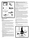
Boat Types (see Figure 1)
• Displacement hull powerboat—Locate 1/3 of the way along
the LWL and 150–300mm (6–12") off the centerline. The
starboard side of the hull where the propeller blades are moving
downward is preferred.
• Planing hull powerboat—Mount well aft near the centerline and
well inboard of the first set of lifting strakes to ensure that it is in
contact with the water at high speeds. The starboard side of the
hull where the propeller blades are moving downward is preferred.
Outboard and I/O—Mount just forward and to the side of the
engine(s).
Inboard—Mount well ahead of the propeller(s) and shaft(s).
Stepped hull—Mount just ahead of the first step.
Boat capable of speeds above 25kn (29MPH)—Review
transducer location and operating results of similar boats before
proceeding.
• Fin keel sailboat—Mount to the side of the centerline and
forward of the fin keel 300–600mm (1–2').
• Full keel sailboat—Locate amidships and away from the keel
at the point of minimum deadrise angle.
Installation: No Fairing or Standard Fairing Only
IMPORTANT: If installing the transducer with NO fairing,
disregard all references to a fairing and backing block.
Hole Drilling
Cored fiberglass hull—Follow separate instructions on page 4.
1. Drill a 3mm or 1/8" pilot hole perpendicular to the waterline from
inside the hull (see Figure 2). If there is a rib, strut, or other hull
irregularity near the selected mounting location, drill from the outside.
2. Using the appropriate size drill bit, cut a hole from outside the
hull. Be sure to hold the drill plumb, so the hole will be
perpendicular to the water surface.
3. Sand and clean the area around the hole, inside and outside, to
ensure the marine sealant will adhere properly to the hull. If there
is any petroleum residue inside the hull, remove it with either a mild
household detergent or a weak solvent (alcohol) before sanding.
Metal hull—Remove all burrs with a file and sandpaper.
Cutting the Standard Fairing
WARNING: High-Performance Fairing—For your safety it is
mandatory to follow the Installation Instructions that come with the
fairing.
CAUTION: The arrow/pointed end of the fairing points forward
toward the bow. Be sure to orient the fairing on the band saw, so
the angle cut matches the intended side of the hull and not the
mirror image.
1. Measure the deadrise angle of the hull at the selected location
using an angle finder (see Figure 2)
2
Figure 1.
pressure waves
1/3
full keel sailboat
displacement hull
(6-12")
fin keel sailboat
150-300mm
LWL
Best location for the transducer
(Load Waterline Length)
stepped hull
planing hulls
hull nut
marine
backing block
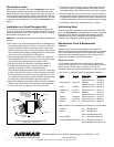
Figure 2. Bedding and installing in a metal hull
6–12mm (1/4–1/2")
Standard Fairing
fairing thickness
hull
(metal)
deadrise
angle
sealant
stem
Aft View
slope of hull
parallel to
waterline
cable
Copyright © 2005 - 2010 Airmar Technology Corp.
Copyright © 2005 - 2010 Airmar Technology Corp.
isolation sleeve
(SS258 with Standard Fairing shown)
transducer
inboard