24/30
¡ Semiconductor MSM66201/66P201/66207/66P207
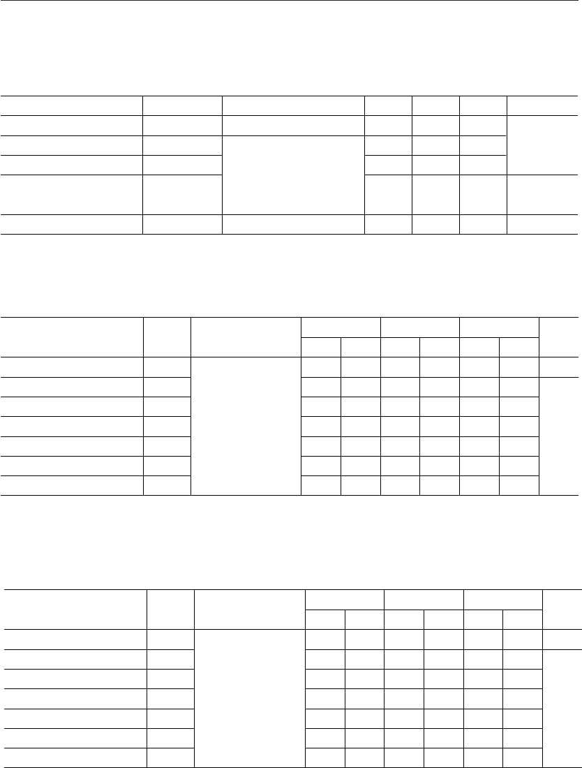
A/D Converter Characteristics
• Operating range
• A/D Converter accuracy
Normal operation mode
Parameter Symbol Condition
Min.
Unit
Resolution
Crosstalk
n
E
A
E
R
E
C
See the
recommended
circuit.
V
R
=V
DD
V
AG
=GND=0V
Analog input source
impedance
£5kW
One channel
conversion time
t
C
=64ms
—
—
—
—
Bit
Absolute Error
Relative Error
*
—
—
—
—
—
—
—
±0.5
*
—
—
—
±0.5
10
+3.0
–3.5
±1.5
*
10
±1.0
Typ. Max.
E
Z
0Zero Point Error 0 — — +3.0 +2.0
E
F
–0.5
LSB
Full Scale Error –1.0 — — –3.5 –3.5
Differential Linearity Error E
D
————
——
+3.0 +2.0
+2.0
–3.5
(V
DD
=5V±10%, f
OSC
=10MHz, Ta=–40 to +85°C)
*V
DD
=5V, Ta=25°C
HALT/HOLD operation mode
Parameter Symbol Condition
Min.
Unit
Resolution
Crosstalk
n
E
A
E
R
E
C
See the
recommended
circuit.
V
R
=V
DD
V
AG
=GND=0V
Analog input source
impedance
£5kW
One channel
conversion time
t
C
=64ms
—
—
—
—
Bit
Absolute Error
Relative Error
*
—
—
—
—
—
—
—
±0.5
*
—
—
—
±0.5
10
+2.0
–3.5
±1.0
*
10
±0.5
Typ. Max.
E
Z
+0.5Zero Point Error +0.5 — — +2.0 +1.0
E
F
–1.0
LSB
Full Scale Error –1.5 — — –3.5 –2.0
Differential Linearity Error E
D
————
——
+2.0 +1.0
+1.0
–2.0
(V
DD
=5V±10%, f
OSC
=10MHz, Ta=–40 to +85°C)
*V
DD
=5V, Ta=25°C
Parameter Symbol Condition Min. Max. Unit
Power Supply Voltage
Analog Reference Voltage
Operating Temperature
V
DD
V
R
V
AI
R
R
T
op
f
OSC
£ 10MHz 4.5
4.5
V
AG
—
–40
5.5
V
DD
V
R
—
+85
V
kW
°C
V
AG
= GND = 0V
Analog Input Voltage
Analog Reference Power
Voltage Resistance
Typ.
—
—
—
16
—V
DD
= 5V ± 10%


