4 – 3
ItemNo. Specification Drawing Adjustment method
Note 1)
The head gap shall be
measured with the
change lever set to
rear position.
Note 2)
The head gap shall be
measured positioning
the platen gear (R)
craw on the top.
Note 3)
Move the adjust
screw in clockwise
direction (in direction
B) to measure.
Measure variation of
gap when range is
changed.
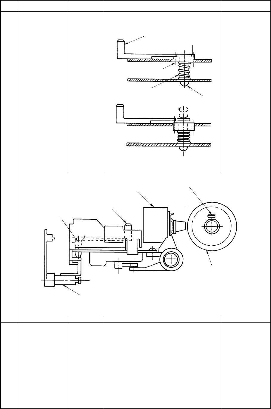
4–1–2 Gap=0.71
±0.05 at the
range 5.
Adjust lever
Adjust gear
Adjust
spring
Adjust
screw
B
C
Adjust lever
Adjust gear
Print head
Click of platen gear R
Platen
Adjust cam
Gap
A


