


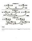

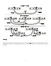
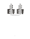
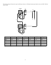
P1 CONNECTOR MAP
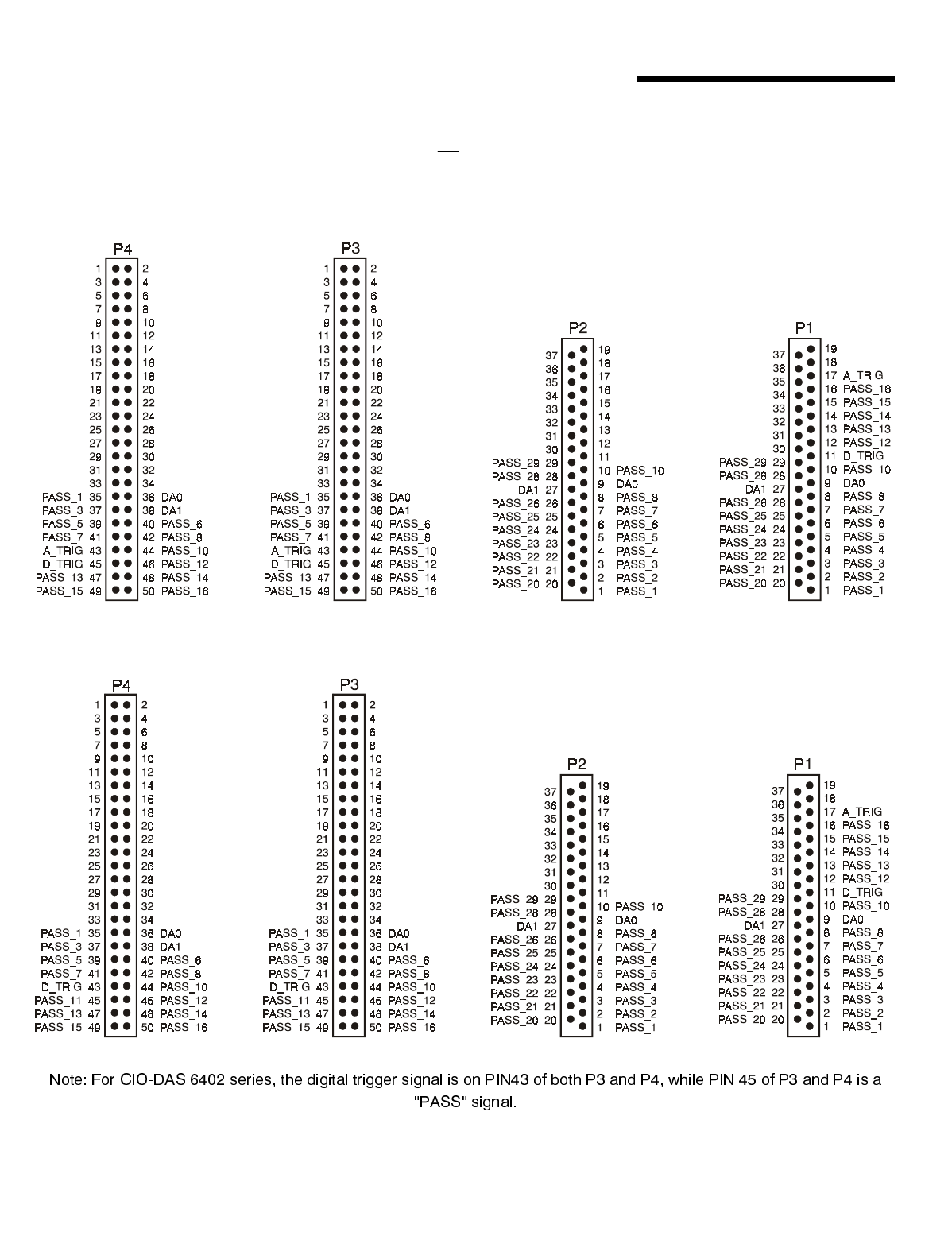
Connector P1 provides the user with a variety of I/O signals, not including the 16 analog input signals from B1-B16. The following
diagram illustrates the connection scheme used to route these signals among connectors P2, P3 and P4 to connector P1. These signals
are labeled “PASS” signals (except for the trigger and D/A options as shown) and the user should consult their DAS manual’s I/O
connector pin assignment section to verify the actual signals available at the P1 connector.
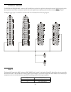
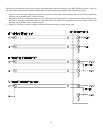
3&RQQHFWRU0DSIRU%1&6(DQG%1&',
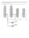
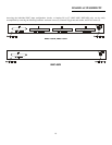
3&RQQHFWRU0DSIRU%1&6(DQG%1&',&,2'$6VHULHVRQO\
12