


5. Register Descriptions
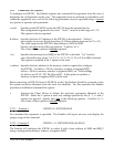
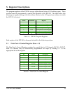
The program registers of the IOP-241 occupy eight adjacent bytes of I/O address space. These
registers must be programmed to control the operation of the IOP-241. The table below lists
the program registers along with their offsets relative to the I/O space base address at which
the IOP-241 is located:
Interrupt Acknowledge Register
W
7
Interrupt Status Register
R
7
Interrupt Mode Control Register
R/W
6
Port C Interrupt Enable Register
R/W
5
Data Port C Control Register
R/W
2
Data Port B Control Register
R/W
1
Data Port A Control Register
R/W
0
RegisterRead/WriteOffset
Table 5-1. IOP-241 Program Registers
Each register of the IOP-241 is discussed in detail in the following sections.
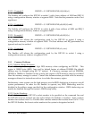
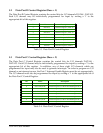
5.1 Data Port A Control Register (Base + 0)
The Data Port A Control Register contains the control bits for I/O channels DATA0 - DATA7.
Each I/O channel may be individually programmed for input by writing a '1' to the
appropriate bit of this register.
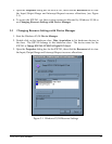
General Purpose I/O bit 0
DATA0
0
General Purpose I/O bit 1
DATA1
1
General Purpose I/O bit 2
DATA2
2
General Purpose I/O bit 3
DATA3
3
General Purpose I/O bit 4
DATA4
4
General Purpose I/O bit 5
DATA5
5
General Purpose I/O bit 6
DATA6
6
General Purpose I/O bit 7
DATA7
7
DescriptionNameBit
Table 5-2. Data Port A Control Register
IOP-241 Users Manual 25