


DaqTemp User’s Manual
09-06-02
Overview & Theory of Operation 1-3
Differential Input Channels (
1H / 1L - 7H / 7L
)
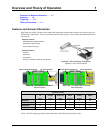
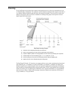
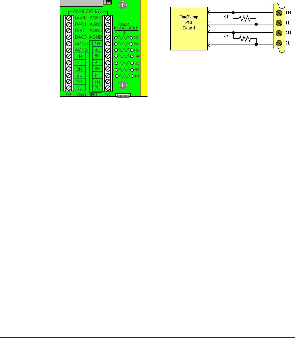
Each DaqTemp model has seven differential input channels for measuring voltage. The voltage channels
are labeled from 1H / 1L to 7H / 7L, with the “H” and “L” representing channel high and channel low.
The seven channels are located on the Analog I/O portion of the card.
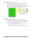
Each differential input channel also has a current shunt resistor that can be user-installed. The resistor will
convert a current to a voltage, the voltage will then be measured by the DaqTemp PCI board. This is a
handy way to measure 4-20mA current loops or make current-based measurements in general. The right-
hand figure shows how the resistors are connected to both the low-side and high-side of each differential
input. Note that R1 is matched to analog input 1, R2 to analog input 2, etc.
Analog I/O Section of DaqTemp
Digital and Analog I/O Card
Differential Input Channels 1 and 2
with User-Installed Resistors
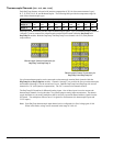
Analog Outputs (
DAC0, DAC1, DAC2, and DAC3
)
The “A” model DaqTemps have Analog Output capability. DaqTemp7A has two digital-to-analog
converters. These are designated as DAC0 and DAC1. DaqTemp14A has four DACs designated as DAC0,
DAC1, DAC2, and DAC3. The DAC channel connections are represented in the above, left-hand figure.
Note that the same Digital and Analog I/O Terminal Block Card is used in all DaqTemp models, regardless
of the unit’s features. Because of this, the following should be realized:
•
DAC2 and DAC3 do not apply to DaqTemp7A. However, the Digital and Analog I/O Terminal
Block Card includes connection labels for DAC2 and DAC3.
•
Analog Outputs do not apply to DaqTemp7 or to DaqTemp14. However, the Digital and
Analog I/O Terminal Block Card includes connection labels for DAC0, DAC1, DAC2, and DAC3.