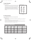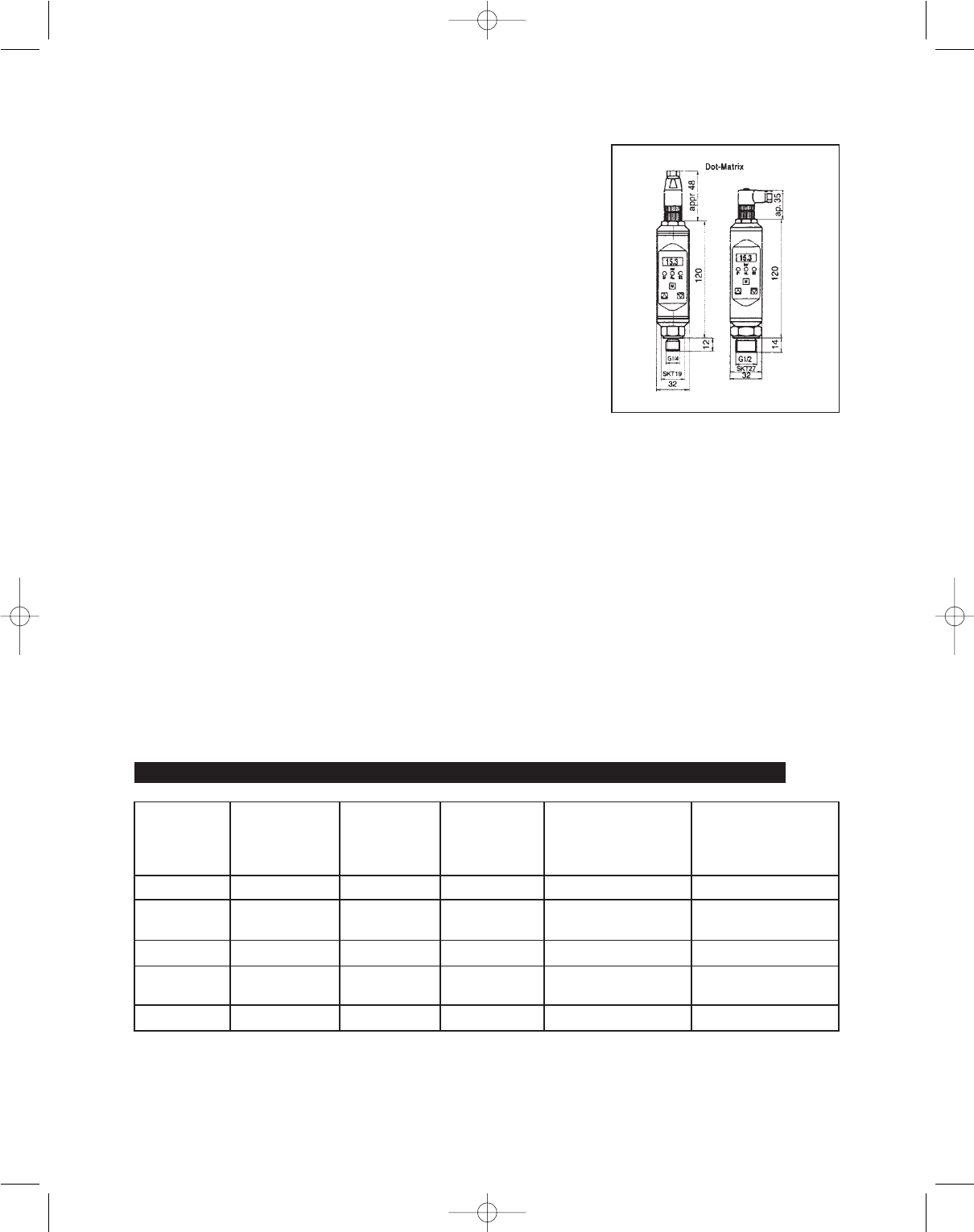
Dimensions (in mm)
3
1. Product Description
2. Starting operations
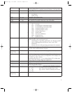
Electrical connections plug 1 (standard) and power supply
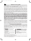
Intended Applications
- The dual pressure switch is a device to monitor system pressure
and has up to two switching outputs and one analog output.
- The instruments must only be installed in systems where the
maximum pressure Pmax or the maximum temperature Tmax is
not exceeded (according to the values on the type label).
- Attention: This device is not designed to be used as the only
safety relevant element in pressurized systems according PED
97/23/EC.
Only assemble or disassemble the device when depressurized!
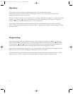
Connecting the switch
- Mount the pressure switch from bottom to the fitting with a wrench hex 19 (1/4“) resp. hex 22
with 45 Nm torque.
- Electrical connection depends on the type of pressure switch (see type label) according to the
chart below (connection chart plug 2 for interface see page 4).
- When display is adjusted (rotable version only) the unit has to be fixed at the front side with
an allen screw and and allen key 1,5 mm (torque = 3 Nm).
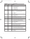
Plug
M 12 x 1
4-pin / 5-pin
PG9 with cable
LifYY11Y
4 / 5x0,25mm
2
Model with 1
switching
output
Model with 2
switching
outputs
Model with 1
switching output
and 1 analog output
Model with 2
switching outputs
and 1 analog output
Pin 1 Brown 18...32 V DC 18...32 V DC 18...32 V DC 18...32 V DC
Pin 2 White - SP2 0,5 A
max.
analog 4...20 mA/
0...10 V DC
analog 4...20 mA/
0...10 V DC
Pin 3 Blue 0 V 0 V 0 V 0 V
Pin 4 Black SP1 0,5 A
max.
SP1 0,5 A
max.
SP1 0,5 A max. SP1 0,5 A max.
Pin 5 Grey - - - SP2 0,5 A max.
PSW1000
PSW1000.qxp 6/5/2008 3:45 PM Page cov-5


