


4
.
7
Interrupt and Status
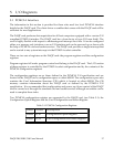
The DAQP card has three interrupt sources, the end-of-scan (EOS) interrupt, the FIFO
threshold interrupt and the timer interrupt. The control register (base + 2, write only) has two
bits to enable or disable the EOS and FIFO interrupts independently. However, it is strongly
recommended that the two interrupts be used exclusively. Bit 5 of the auxiliary control
register (base + 15, write only) enables or disables the timer interrupt.
When the EOS interrupt is enabled, an interrupt is sent to the host at the end of each scan of
the channel list. If there is only one channel in the scan list, the EOS interrupt is reduced to an
EOC (end-of-conversion) interrupt.
The FIFO threshold interrupt, when enabled, is sent to the host when the almost full flag is set.
The host can then use the “string input” instruction to move a block of samples from the FIFO.
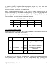
The EOS and FIFO threshold event bits in the status register (base + 2, read only) and will be
set whenever the corresponding event happens. These bits can be used for indicating the
source of the interrupt. Once set, the event bits will not be cleared until the host reads the
status register.
When the timer interrupt is enabled, an interrupt is sent to the host whenever the timer
overflows. The corresponding event bit is in the auxiliary status register (bit 4 at base +15,
read only). Reading the register will not clear this event. It can only be cleared by writing a “0”
to bit 5 of the auxiliary control register which disables the timer interrupt.
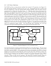
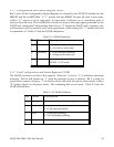
4.8 Digital I/O
The DAQP card has one digital input port (base + 3, read only) of four bits (bits 0-3), and one
digital output port (base + 3, write only) of four bits (bits 0-3). The output port is latched, but
the input port is not.
Four input lines are connected to the digital input port, each representing one bit in the port.
When reading the digital input port, the CURRENT status of the digital input lines are
returned to the host.
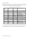
All four input lines are shared with other functions. Bit 0 is shared as the external trigger
input, while bit 2 is shared as the external clock input. Bits 1 and 3 are taken over as the
external gain selection lines if there is an expansion card(s) connected and the expansion bit in
the control register is set to ‘1’. In this case, the digital output lines are driven by the external
channel selection bits of the current scan list entry. Otherwise, they will be connected to the
latched bits 0-3 of the digital output port. The current status of the digital input lines will
always be returned when the host reads the digital input port regardless of whether the lines
are shared or not.
DAQP-208/208H/308 Users Manual 33