


M-4271/0707, pg. 11 of 26
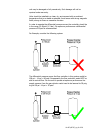
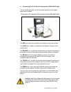
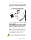
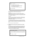
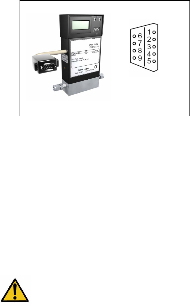
d) Connections For The 9 Pin D Sub Connector
Using a suitable mating connector the pins of the integrated connector
should be wired as follows:
Connecting To The Integrated 9 Pin Connector
PIN 3 should be connected to the Positive of the power source.
PIN 4 should be connected to the Negative ( Ground ) of the power
source.
PIN 2 provides the signal output and should be connected to the positive
terminal of the display, data acquisition system or voltmeter.
PIN 8 is the signal negative (ground) and should be connected to the
negative (Ground) terminal of the display, data acquisition system or
voltmeter.
Pin 6 is the input signal and should be connected to the positive terminal
of the voltage source. The (0-5VDC) voltage control signal should be
supplied from a low impedance source.
Pin 7 is the input signal negative (ground) and should be connected to
the negative (Ground) terminal of the voltage source.
Pins 1, 5, and 9 are not used.
Caution: Avoid high voltage static discharges to the input signal
connection. Do not short the input/output signal pins or allow
them to contact the power connections at any time. DAMAGE
WILL RESULT!
Pin Out of Integrated
Connector