


M-4271/0707, pg. 10 of 26
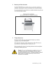
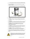
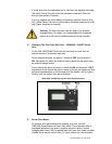
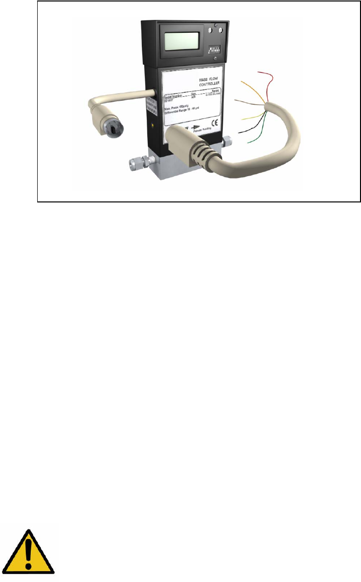
c) Connecting The 6 Pin Mini Din Connector & FMA 3000C Cable
The two mating connectors should be pushed together and the pigtail
leads wired as follows:
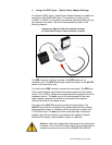
Connecting To The Integrated 6 Pin Connector Using A FMA 3000C Cable
The RED wire should be connected to the Positive of the power source.
The BLACK wire should be connected to the Negative (Ground) of the
power source.
The ORANGE wire provides the signal output and should be connected to
the positive terminal of the display, data acquisition system or voltmeter.
The BROWN wire is the signal negative (ground) and should be
connected to the negative (Ground) terminal of the display, data
acquisition system or voltmeter.
The YELLOW wire provides the input signal and should be connected to
the positive terminal of the voltage source. The (0-5VDC) voltage control
signal should be supplied from a low impedance source.
The GREEN wire is the input signal negative (ground) and should be
connected to the negative (Ground) terminal of the voltage source.
The wire colors above describe the pigtail leads of the FMA 3000C cable
assembly and may not correspond with the internal wiring of your flow
sensor.
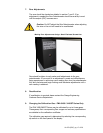
Caution: Avoid high voltage static discharges to the input signal
connection. Do not short the input/output signal wires or allow
them to contact the power wires at any time. DAMAGE WILL
RESULT!