


8
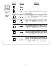
LOCK - This portion of the menu allows you to:
1) lock the program (presets are still accessible)
2) lock all (presets and program are locked).
LOCK PROGRAM - This will lock the program and allow the presets to be changed when the unit is in the
lock mode.
LOCK ALL - This will lock the program and the presets when the unit is in the locked mode. The presets can
be viewed, but not changed.
LOCK CODE - This message (code) will flash on display for approximately 3 seconds. It will be followed by a
5 digit number (xxxxx). The number you enter here will be the code to lock and unlock the unit.
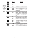
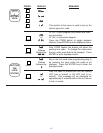
RELAY - This portion of the menu allows you to set your relay operation variables.
RELAY A FOR TOTALIZER - When this is selected relay A will activate when the net total has reached
Preset A ("A NET B" Mode ). Relay A will activate when the total of input A reaches preset A ("A SEP B"
Mode).
RELAY A FOR RATE - When this is selected relay A will activate when the Rate of input A equals or exceeds
preset A when in "A NET B" or "A SEP B" mode. The relay will drop out when the rate of A falls below preset
A.
RELAY A DURATION - This message will appear when "A TOT" is selected. It is the duration which the
relay will remain energized (00.1 to 99.9 sec). If 00.0 is selected, the relay will latch until reset. When the
duration is not at 00.0, the unit will autorecycle.
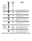
RELAY B FOR TOTALIZER - When this is selected relay B will activate when the net total has reached preset
B ("A NET B" Mode). Relay B will activate when the total of input B has reached preset B ("A SEP B" Mode).
RELAY B FOR RATE - When this is selected relay B will activate when the rate of input A equals or exceeds
preset B when in "A NET B" or "A SEP B" mode. The relay will drop out when the rate of A falls below preset
B.
RELAY B DURATION - Follow same procedure as A ##.#.
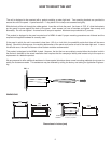
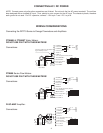
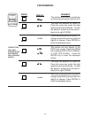
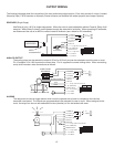
TERMINATIONS
1 2 3 4
REAR VIEW
1 2 3 4 5 6 7 8 9 10 11 12
13 14
Analog Out Setup SwitchesSerial Port
ON
RELAYS
A
B
13- V+
14- I SINK
ANALOG
OUTPUT
ON
CAL.
0-20mA
COUNT
SET
OFF
RUN
4-20mA
RATE
RUN
1 2 3 4
ON
SWITCH
1- COMMON
2- N.O.(N.C./NPN)
3- COMMON
4- N.O.(N.C./NPN)
5- INPUT A
6- INPUT B
7- 11 - 19 V @ 50mA OUT/+DC IN
8- -DC (GROUND)
9- RESET INPUT
10- 6 - 14 V @ 50mA
11- A.C. INPUT
12- A.C. INPUT