


Page : 10
9.2.2.- CONNECTION EXAMPLES
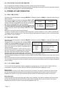
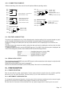
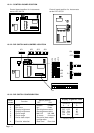
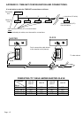
Different interlinking of the three control lines will produce different operating modes:
Close contact A = reset and run
Open contact A = stop
Stop
Start
Reset
GND
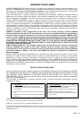
Stop
Start
Reset
GND
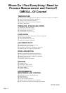
Stop
Start
Reset
GND
With contact B opened
close contact A = run
open contact A = stop
push contact B = reset
A
A
A
B
B
Push A = start
Push A = stop
Push B = reset
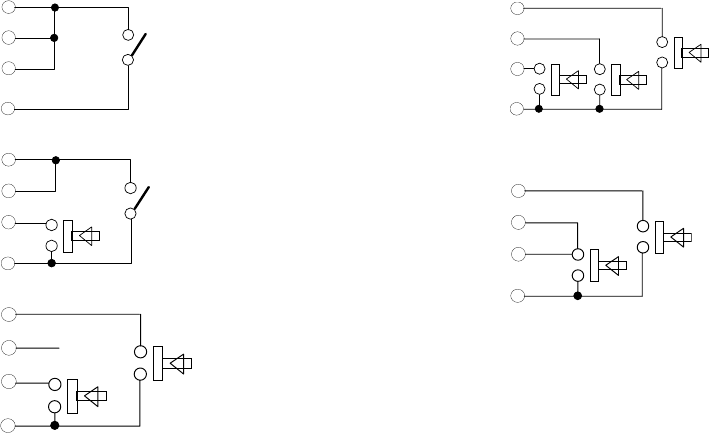
Stop
Start
Reset
GND
A
B
C
Stop
Start
Reset
GND
A
B
Push A = reset and start
Push B = stop
(push B again = start)
Push B = start
Push A = stop
Push C = reset
note A may close while B
is shut
B may open while A is shut
9.3.- RUN TIME ALARM SETTING
The alarm is a 4 decade alarm only. On the 6 decade clock, the alarm setting is for hours and minutes only and
on the 4 decade clock the alarm point can be for either hours and minutes or minutes and seconds.
Displaying or setting of the alarm point can only be done when the unit is displaying the run time and is not
running.
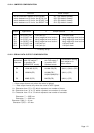
The same three contact inputs are used for setting the alarm point and for adjusting the real time clock, but their
functions are different.
To display the alarm set point, hold the SECONDS input (pin 13) to GND. Once the alarm point is displayed, the
value can be changed by contact closure between GND and the following terminals :
Seconds ........................... view/adjust alarm point ( hold to GND).
Minutes ............................ increment seconds ( or minutes).
Hours ............................... increment minutes ( or hours).
Hours and Minutes .......... together reset alarm to zero
9.4.- SERIAL DATA OUTPUT
The unit incorporates and RS422 level serial ASCII output to allow master/slave clock setups in conjunction with
serial ASCII remote displays.
Details of the serial output to be found in paragraph 5.
Note the line should be terminated to prevent noise pickup if the clock is not transmitting data.
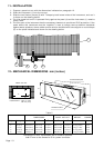
10.- CONFIGURATION
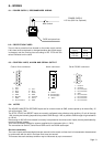
10.1.- POWER SELECTION
See the rear label for power requirements. Power supply selection must be done by suitable qualified
personnel or by the local distributor. Contact factory or your local distributor for instructions.
10.2.- INSTRUMENT CONFIGURATION
To change the instrument configuration, the rear panel of the instrument needs only to be removed to gain
access to the internal DIP switches and jumpers located on the control board.
Be sure that the instrument is disconnected from any power supply before removing the rear panel.