


Page : 6
OUTPUTS
SERIAL OUTPUT . . . . . . . Output intended for transmission to the
remote display fitted with a clock
display as a slave clock display.
Signal . . . . . . . . . . . . . . . . RS422 level 1200 baud fixed rate. One
transmission each second while
showing real time or run time.
String . . . . . . . . . . . . . . . . . Transmits --NUL--(CR)
or --NUL--NUL--(CR) when setting time
or entering alarm state.
Data string
Standard mode . . . . . HH.MM.SS for 6 decade version.
HH.MM or MM.SS for 4 decade version.
Newport mode . . . . . . HHM.MS.S for 6 decade version.
HHM.M or MMS.S for 4 decade version.
Character length . . . . . . . . One start bit, 8 data bits no parity and
one stop bit.
Handshake . . . . . . . . . . . . No handshake : one data string
transmitted each second.
EXCITATION VOLTAGE OUTPUT
Vexc . . . . . . . . . . . . . . . . . +15 Vdc ±20%. @100 mA. max.
Ripple . . . . . . . . . . . . . . . . 100 mVac 50/60 Hz.
ENVIRONMENTAL
Temperature
Operating . . . . 0 to +50 ºC (32 to 122 ºF).
Storage . . . . . . -20 to +85 º C (-4 to 185 ºF).
Relative humidity . . . . . . . . 0 to 85 % not condensed.
Protection . . . . . . . . . . . . . IP65. (Front part only).
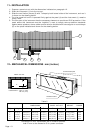
MECHANICAL
Dimensions . . . . . . . . . . . . See table in page 13.
Panel cut out . . . . . . . . . . . See table in page 13.
Depth . . . . . . . . . . . . . . . . . See table in page 13.
Weight . . . . . . . . . . . . . . . . See table in page 13.
Case material. . . . . . . . . . . Aluminium extruded.
Finished . . . . . . . . . . . . . . . Anodized, black colour.
ELECTRICAL
Standard power supply . . . 115 Vac. ±10% 50 / 60 Hz.
(230 Vac optionally)
Consumption . . . . . . . . . . . See table in page 13.
5.- GENERAL SPECIFICATIONS
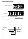
DISPLAY
Type . . . . . . . . . . . . . . . . . 4 or 6 digits, 7 segments, red or green LED.
Height digit . . . . . . . . . . . . 57 (2.3") or 100 mm. (4")
Range máx. . . . . . . . . . . . . 99 : 59 or 99 :59 : 59
Brightness . . . . . . . . . . . . . Set by switch for 25%, 50%, 75%
or 100% (normal).
REAL TIME CLOCK.
Type . . . . . . . . . . . . . . . . . 59 mm 59 ss (model C0)
12/24 hours selectable
Time setting . . . . . . . . . . . . By volt free contact closure inputs
seconds reset, minutes advance
and hours advance.
Time accuracy . . . . . . . . . . ±1 minute per month.
Power down . . . . . . . . . . . . Maintains time for minimum 2 years
without mains power.
RUN TIME CLOCK
Type . . . . . . . . . . . . . . . . . 99 mm 59 ss, 99 hh 59 mm
or 99 hh 59 mm 59 ss
Timer resolution . . . . . . . . . 1 second.
Timer uncertainty . . . . . . . . 1 second max. per start/stop sequence.
Timer memory . . . . . . . . . . Run time maintained for 2 years minimum
but not updated with mains removed.
Alarm . . . . . . . . . . . . . . . . . One minute or one second resolution
(one minute only on model C2) set by
external closure inputs.
Alarm enable . . . . . . . . . . . Controlled by internal switch.
Alarm output . . . . . . . . . . . Optically isolates transistor switch
30 V / 30 mA capacity.
Alarm indication . . . . . . . . . Clock stop, display flashes and alarm
output activates.
Initialization . . . . . . . . . . . . By operation of one or more the
control inputs.
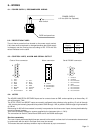
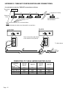
CONTROL LINES
Type . . . . . . . . . . . . . . . . . Three inputs sharing one common return.
Threshold . . . . . . . . . . . . . Rising : +2.3 V min., +3.6 V max.
Falling : +0.9 V min., +2.5 V max.
Signal hysteresis . . . . . . . . 0.4 V minimum.
Maximum signal . . . . . . . . . ±30 V.
Loading . . . . . . . . . . . . . . . 100 KΩ to common for +5 V signal
18 KΩ loading beyond +5/-0.6V.
Load . . . . . . . . . . . . . . . . . 1 KΩ ±5% load may be internally
jumpered to common or to the excitation
supply for each control line.
Response time . . . . . . . . . . 200 mS maximum: internally
debounced for contact closure inputs.
Active level . . . . . . . . . . . . . Internally jumpered to be active either with
low level/falling edge or high level/rising
edge inputs independently for each
control line.
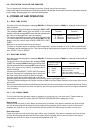
CONTROL MODES
Type . . . . . . . . . . . . . . . . . The operating mode depends on
interlinking of the three control lines.
One control . . . . . . . . . . . . To reset and run when active and stop
when inactive.
Two controls . . . . . . . . . . . One to run when active and stop when
inactive and the other to reset.
Two controls . . . . . . . . . . . One to alternately start and stop and the
other to reset.
Three controls . . . . . . . . . . One to start, one to stop and one to
reset.