


GENERAL
Pressure variations are sensed by a bellows, diaphragm or piston
sensor which either actuates or de-actuates one, two or three snap-
acting switches at a pre-determined set point(s). Set point(s) is
adjusted by turning an internal knob and pointer or internal screw
Tools Needed
Screwdriver
Hammer
Adjustable wrench
MOUNTING
INSTALL UNIT WHERE SHOCK, VIBRATION AND
TEMPERATURE FLUCTUATIONS ARE MINIMAL.
ORIENT UNIT SO THAT MOISTURE IS
PREVENTED FROM ENTERING THE ENCLOSURE. IF UNIT
IS BEING INSTALLED WHERE HEAVY CONDENSATION IS
EXPECTED, VERTICAL MOUNTING
(PRESSURE CONNECTION DOWN) IS REQUIRED. DO NOT
MOUNT UNIT IN AMBIENT TEMPERATURES EXCEEDING
PUBLISHED LIMITS.
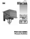
PSW-850 Series pressure controls can be mounted in any
position, provided the electrical conduit is not facing up. The
preferred mounting position is vertical (pressure connection
down).
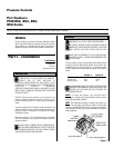
The cast-in knockouts for 3/4” electrical conduit are located on the
side and rear of the enclosure. These can easily be knocked out by
placing the blade of a screwdriver in the groove and rapping
sharply with a hammer.
Mount the unit via the (2) 1/4” screw clearance holes on the enclo-
sure. See Dimensions. Units may also be mounted via the NPT
pressure connection.
ALWAYS HOLD A WRENCH ON THE PRESSURE HOUS-
ING HEX WHEN MOUNTING UNIT. DO NOT TIGHTEN BY
TURNING ENCLOSURE. THIS WILL DAMAGE SENSOR
AND WEAKEN SOLDER OR WELDED JOINTS.
Please read all instructional literature carefully and thoroughly before starting.
Pressure Controls
Part Numbers:
PSW-852, 853, 855,
856 Series
Part I - Installation
WIRING
DISCONNECT ALL SUPPLY CIRCUITS BEFORE WIRING.
ELECTRICAL RATINGS STATED IN LITERATURE AND ON
NAMEPLATE SHOULD NEVER BE EXCEEDED. OVER-LOAD
ON A SWITCH CAN CAUSE FAILURE ON THE FIRST
CYCLE.
WIRE UNITS ACCORDING TO LOCAL AND NATIONAL
ELECTRICAL CODES. MAXIMUM RECOMMENDED WIRE
SIZE IS 14 AWG.
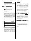
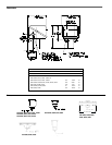
Connect conduit to the case and wire directly to the switch terminals
according to local and national electrical codes. Bring the wires up to
terminals from the rear of the case. (See fig. 1.) If manual reset switch
or DPDT options are used, lead wires are supplied, color coded as
follows:
ALLOW ENOUGH SLACK SO AS NOT TO AFFECT SWITCH
MOVEMENT WHEN MAKING SETTING ADJUSTMENTS AND
ENSURE THAT THE WIRES ARE NOT TOUCHING THE
COVER WHEN INSTALLED.
NOTE: For larger wire gauges, a one time shift may be
experienced or expected due to space limitations within the enclo-
sure. Verify setpoint after installation.
NOTE: The middle switch assembly is omitted for dual switch con-
trollers. The outer switch assemblies are omitted for single switch
controllers. Type PSW-852, 853 controls have internal screw adjust-
ments and type PSW-855, 856 have cam assemblies for internal cali-
brated adjustments.
Switch 1 Switch 2
Common Violet Yellow
Normally Open Blue Orange
Normally Closed Black Red
Figure 1